Re: Re: 1st PCB ever
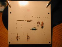
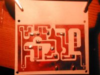
Now the board looks ok but I can not remove the paint over the copper easily. I tried nail remover "acetone" and the paint comes off but smudges the board (White glass fiber now becoming black "I doubt the paint dielectric properties"). I searched for lacqer thinner but can not find it easily in Portugal. Can I try regular celulosic thinner ?
Ricardo
Yesterday I etched the schunt board. Very messy procedure, my lungs "and my wives" where affected and I do not know how to dispose the used etchant !!!ikoflexer said:
Nice board Ricardo! Well done. Once you find the proper paper for the transfer, you will not see many flaws at all. It is also important to press decidedly with the iron edge (or tip) in one place repeatedly, Also, when printing it, the printer has to be set to the darkest setting (done in properties in software, advanced option). They also sell special transfer paper in electronics parts stores, but it's a bit pricey.
When I have to retouch, I use black nail polish (donated somewhat reluctantly by my wife).
Now the board looks ok but I can not remove the paint over the copper easily. I tried nail remover "acetone" and the paint comes off but smudges the board (White glass fiber now becoming black "I doubt the paint dielectric properties"). I searched for lacqer thinner but can not find it easily in Portugal. Can I try regular celulosic thinner ?
Ricardo
kstlfido:
In your case it was the small heat sinks. You had 120mA running and you reduced to 100mA. Iko must measure his current draw and given his heat sinks maybe save off 50mA from his 200mA target, if heat sinks are small or check the quality of heat transfer, maybe some smoothing of the sink's back with sand paper and some silicone grease if not used already. If the LEDS are stronger than recommended it may well over shoot the 200mA target also. Those Mosfets are strong, but better be conservative for long life. In any case, we use plenty of current here for quality reasons and we can always reduce some, if our sinks end up rather small for what we originally set.
In your case it was the small heat sinks. You had 120mA running and you reduced to 100mA. Iko must measure his current draw and given his heat sinks maybe save off 50mA from his 200mA target, if heat sinks are small or check the quality of heat transfer, maybe some smoothing of the sink's back with sand paper and some silicone grease if not used already. If the LEDS are stronger than recommended it may well over shoot the 200mA target also. Those Mosfets are strong, but better be conservative for long life. In any case, we use plenty of current here for quality reasons and we can always reduce some, if our sinks end up rather small for what we originally set.
nicoch46 said:just if you have suggention on pcb design.....
the guys make good works, can do better ?
I am no PCB expert. I do point to point, you know. I would try to exploit the PCB opportunity so to be more creative with grounding if I was making one, sub stars, separation of nodes, ground planes, very compact gain stages, such stuff I guess.
nicoch46 said:
pcb design is a art ,hope this help and I do not know more
Tomo you make a discount on box for Salas gang ?
PCB design is something I quite enjoy, but it does take practise and I still have lots to learn.
I shall do my absolute best to help out anyone of this forum/thread with good prices on cases or parts or anything. It's the least I can do in return for all the help and advice I've received.
Regards,
Lee.
Thomo said:Hi guys. I just swapped the 100nF cap from a Mundorf Supreme, to a Russian Paper in Oil 47nF and got quite an improvement! Treble is definitely better and mids seem more open. The soundstage also seems more 3d.
I am really surprised by this, as the Supreme's are really great caps.
Hi Lee
Those are very good news. I believe that seetles my decision regarding the coupling cap
kstlfido said:Jeez- lame-o review dumped attachment..here it is-
-K
Kent, that is one PRETTY board. Very nice indeed!
caps
some links on caps-resistor test
http://www.tempoelectric.com/caps.htm
http://www.sasaudiolabs.com/resistor.htm
http://www.ecp.cc/cap-notes.html
http://www.audiocircle.com/circles/index.php?PHPSESSID=mphia6n8li541l20o6mm11si34&topic=54218.0--
I post too much today
some links on caps-resistor test
http://www.tempoelectric.com/caps.htm
http://www.sasaudiolabs.com/resistor.htm
http://www.ecp.cc/cap-notes.html
http://www.audiocircle.com/circles/index.php?PHPSESSID=mphia6n8li541l20o6mm11si34&topic=54218.0--
I post too much today
nicoch46 said:HI Cruz
I see that you mod a lot your meridian ......
by the way he have metal shield around phono ,a simple psu design and one opa-amp ,buffer?
I thinks the Salas phono-shunt are super design ,DIY are always better
you can thinks a pot like otptivol and connect direct to amp
I modded the Meridian PSU (with stupefyingly good results) and replaced the coupling cap between the Head amp and the Riaa.
There is no metal shield on the Riaa (only a plastic cover that I removed). (As a matter of fact, the +-15v rayregs I built are quite close to the head amp).
Layout is like: MM head Amp -> 100uF BG Nx 6.3v -> Riaa -> 10k linear pot -> output metal can opamp -> no output caps to the 103 pwer amp.
Sounds fabulous but I want to get rid of the opamp.
I believe I will build a preamp using Salas Riaa -> 50k linear pot -> buffer -> output to the 103 power amp.
Ricardo
Note: At lunch time I used Dyrup 8004 celuloid thinner and the ink just dispeared... (also ate the Paterson Photo cuba I was using for the bath "Dustbined").
Tonight I will drill the holes, than clean up with Duraglit.
Latter I will build the schunt (parts = +-15€
)I do not know if it can be better than the expensive Spower (this sreg can output 5Amps heavily heatsinked and sounds wonderfull in my CDP jfet output stage) but I am following the threads indications.
Hope my new preamp can drive the 103 power amp without any fuzz.
Attachments
IRFP9240 can handle 12A 200V. I have designed a shunt for a friend at 13V 3A, he will use it soon for his T-Amp, both channels. Nice loons we are, a cool running digital amp, with a hot linear shunt.
As you see RCruz, the cost for my shunt is low, and is nice to make something DIY. Keep it to directly compare SPower on the JFET phono, and let us know. If SPower proves better, we converge to it.
As you see RCruz, the cost for my shunt is low, and is nice to make something DIY. Keep it to directly compare SPower on the JFET phono, and let us know. If SPower proves better, we converge to it.
Re: Re: Re: 1st PCB ever
Ricardo, sorry to hear about the lungs. Did you warm up the etchant? Do you use ferric chloride? That's what I used, but I don't warm it up. I just fill in the sink with hot water, to keep the etchant warm, and place a thin wall tray in that warm water. The tray holds the etchant, but it does not smell at all. Then with a brush, I continuously brush the board surface to speed things up a bit. It's slower than if you heat up the etchant, but healthier.
As for disposing the etchant. You can re-use it quite a few times. When it's no longer good, you should search in your local city about disposing of hazardous chemicals.
RCruz said:
Yesterday I etched the schunt board. Very messy procedure, my lungs "and my wives" where affected and I do not know how to dispose the used etchant !!!
Now the board looks ok but I can not remove the paint over the copper easily. I tried nail remover "acetone" and the paint comes off but smudges the board (White glass fiber now becoming black "I doubt the paint dielectric properties"). I searched for lacqer thinner but can not find it easily in Portugal. Can I try regular celulosic thinner ?
Ricardo
Ricardo, sorry to hear about the lungs. Did you warm up the etchant? Do you use ferric chloride? That's what I used, but I don't warm it up. I just fill in the sink with hot water, to keep the etchant warm, and place a thin wall tray in that warm water. The tray holds the etchant, but it does not smell at all. Then with a brush, I continuously brush the board surface to speed things up a bit. It's slower than if you heat up the etchant, but healthier.
As for disposing the etchant. You can re-use it quite a few times. When it's no longer good, you should search in your local city about disposing of hazardous chemicals.
nicoch46 said:ikoflexer if you do new pcb better use , 0.1mf at input of B+ to avoid pickup rfi from cable
and for gnd you can see the separate signal gnd trace ,this little difference are impontant (separate local loop),walk + and- in pair were possible, and carry a separate wire from psu for gnd ,do not cross on pcb and do not connect the out rca gnd
pcb design is a art ,hope this help and I do not know more
from JC discussion the box for bullprof from rfi need alu trick 10mm
Tomo you make a discount on box for Salas gang ?
Thank you for all suggestions. I wanted to put together a basic pcb layout for myself, to just make it easier to quickly build the preamp, and decided to share the layout in case somebody else might find it useful. I would improve it if I knew how. Perhaps someone who knows more can just do it.
For Ken's layout it probably is very easy to separate power and signal ground; it seems that only Vin, the diode, and the three electrolythics are connected to power ground.
Re: Re: Re: Re: 1st PCB ever
Hi ikoflexer
There was no smell, I did mix the ferric chloride cristals with warm water to make the etchant but did not heat it afterwards. No smell but a funny feeling in the respiratory system... my wife kept coughing...
Maybe I should have done it in an open space and not inside the house. Nevertheless there was no harm...!
Ricardo
ikoflexer said:
Ricardo, sorry to hear about the lungs. Did you warm up the etchant? Do you use ferric chloride?
The tray holds the etchant, but it does not smell at all.
Hi ikoflexer
There was no smell, I did mix the ferric chloride cristals with warm water to make the etchant but did not heat it afterwards. No smell but a funny feeling in the respiratory system... my wife kept coughing...
Maybe I should have done it in an open space and not inside the house. Nevertheless there was no harm...!
Ricardo
Populating the schunt... that is the question
Hi Salas
I am already populating the shunt pcb.
As I collected all the parts locally, I am having some trouble with the quality of the resistors and leds.
Refering to your last post 728 http://www.diyaudio.com/forums/showthread.php?postid=1722356#post1722356 about the +28V with leds, I would like to know if there is some flexibility about the values:
R1 (6.8R 1W) - I have got 7.4R 1W.. can it be used ?
Leds - Green "normal ogive type" .. Are these determinant in the output voltage ? If so, how can I check the leds dropout voltage ?
C1 C2 (100uF 10v // 35v) can I use other values ? 120u ? are these determinat in the output voltage ? Any of those needs to be low noise / low esr ?
Looking good....
Ricardo
Attachments

salas said:Get Panasonic FC. Normal price...
Normal price??? Please try
http://www.reichelt.de/?;ACTION=3;L...wQASAAACc0zQA00f8d5741d062e30c9084e4b2183c2a1
All FC with nice price here
http://www.reichelt.de/index.html?;...wQASAAACc0zQA00f8d5741d062e30c9084e4b2183c2a1
Carsten
carawu said:
Normal price??? Please try
Carsten
Normal price VS boutique caps I meant, and maybe normal for Panasonic FC in North America I guess. In Europe they are cheaper. Anyway they are the best value for money electrolytics by far for audio.
Re: Populating the schunt... that is the question
Yes you can use R1=7R4. That resistor and the total LEDS voltage drop determine the ICCS current. There is the VGS tension inherently about 3.4V for IRFP9240 at voltages used here. The 3 LEDS develop Vtotal=3XLEDVdrop. If they are 1.7V each as on schematic, then Vtotal=5.1V. ICCS=(Vtotal-VGS)/R1=250mA if R1=6R8 or 230mA if R1=7R4. Best thing than to worry about what LEDS you are using and to avoid matching them, is to fire the shunt up for a minute, and just measure the Vdrop across them. Then you can determine a suitable R1 by the above formulas I gave. My recommendation would be 200-250mA depending on your sinking. At about 200mA and above its transient behavior is concrete. Your real need for both channels of your phono is for 40mA idle. With 200mA you get a royal current margin for quality dynamics, and 200mA-40mA=160mA at 28V. 4.5W idle dissipation from your shunt Mosfet can be easy to sink IMO. I use a 230mA CCS for 20mA total consumption in mine (no buffers), for months now, 24H/7d on. No problems, and my heat sink is just the thin metal floor of my half width box. I recommended green 1.7V LEDS for typical reasons. I.e. they don't vary much their Vdrop in green color, and the given R1 gives nominal CCS current with them (there is not a 200mA typo on that link, its an ''about'' value given there will be VGS tolerance between IRFP9240s). A schematic has to anchor somewhere, but now you know how to manipulate it. (I have refered some times before in the thread on that).
Yes you can use other bigger values for those local noise filter capacitors. Better be low ESR, but nothing really fancy. No they don't determine any voltages, the Zener and the BJT Vbe does that. Just don't change the uF value of Cout if you can (I have determined its transient termination best value), and use there the best you can. More capacitor Voltage value than 35V in your shunt, no problem.
RCruz said:Hi Salas
I am already populating the shunt pcb.
As I collected all the parts locally, I am having some trouble with the quality of the resistors and leds.
Refering to your last post 728 http://www.diyaudio.com/forums/showthread.php?postid=1722356#post1722356 about the +28V with leds, I would like to know if there is some flexibility about the values:
R1 (6.8R 1W) - I have got 7.4R 1W.. can it be used ?
Leds - Green "normal ogive type" .. Are these determinant in the output voltage ? If so, how can I check the leds dropout voltage ?
C1 C2 (100uF 10v // 35v) can I use other values ? 120u ? are these determinat in the output voltage ? Any of those needs to be low noise / low esr ?
Looking good....
Ricardo
Yes you can use R1=7R4. That resistor and the total LEDS voltage drop determine the ICCS current. There is the VGS tension inherently about 3.4V for IRFP9240 at voltages used here. The 3 LEDS develop Vtotal=3XLEDVdrop. If they are 1.7V each as on schematic, then Vtotal=5.1V. ICCS=(Vtotal-VGS)/R1=250mA if R1=6R8 or 230mA if R1=7R4. Best thing than to worry about what LEDS you are using and to avoid matching them, is to fire the shunt up for a minute, and just measure the Vdrop across them. Then you can determine a suitable R1 by the above formulas I gave. My recommendation would be 200-250mA depending on your sinking. At about 200mA and above its transient behavior is concrete. Your real need for both channels of your phono is for 40mA idle. With 200mA you get a royal current margin for quality dynamics, and 200mA-40mA=160mA at 28V. 4.5W idle dissipation from your shunt Mosfet can be easy to sink IMO. I use a 230mA CCS for 20mA total consumption in mine (no buffers), for months now, 24H/7d on. No problems, and my heat sink is just the thin metal floor of my half width box. I recommended green 1.7V LEDS for typical reasons. I.e. they don't vary much their Vdrop in green color, and the given R1 gives nominal CCS current with them (there is not a 200mA typo on that link, its an ''about'' value given there will be VGS tolerance between IRFP9240s). A schematic has to anchor somewhere, but now you know how to manipulate it. (I have refered some times before in the thread on that).
Yes you can use other bigger values for those local noise filter capacitors. Better be low ESR, but nothing really fancy. No they don't determine any voltages, the Zener and the BJT Vbe does that. Just don't change the uF value of Cout if you can (I have determined its transient termination best value), and use there the best you can. More capacitor Voltage value than 35V in your shunt, no problem.
- Home
- Source & Line
- Analogue Source
- Simplistic NJFET RIAA