ikoflexer said:I was going to do the Gary Pimm tube phono stage next, but
Gary Pimm's is one of the very few really worthwhile valve DIY things out there along with Steve Bench's. For easy and fast making, easy changing to MC, no step ups, certainly low noise, better start with the JFET though. Terribly cheaper than the tube ones and very close to character.
nicoch46 said:strange I build 4 amp never have one problem...
by the way the classD suck ,better you look at Mr Pass or similar
")
I got the soldering wrong (shorts) and all hell broke loose. Now, that's surprising, to hear someone that has a truepath saying that it sucks
) One thing is sure, I don't think I'll go down that road again. Mr. Pass's work looks very impressive, never heard one though. Any particular one you'd recommend?And not to be totally off topic, I got the 2sk170 so I hope to get a prototype finished this weekend. Can't wait to hear what it can do.
ikoflexer said:And not to be totally off topic, I got the 2sk170 so I hope to get a prototype finished this weekend. Can't wait to hear what it can do.
Related ideas and open discussion are never off topic in my thread.
To hear what it can do, there are a few things to be well aligned (TT, gain, ancillaries, parts quality), so all that are in topic.
nicoch46 said:Toronto
nice place for hot class A
F5 or miniA
As usual Salas know better then me.....
PS
truepath is good but not HI-End, and my amp is not so hiend
for now
That's right
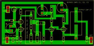
we could use some class A heaters. I'll have a look at those, thanks.Well, guys, I think I might be ready for the phono pcb. Any suggestions/opinions welcome.
Attachments
And here are the files needed to print from expresspcb to create a board.
The way I create a board is by printing on a laser printer onto glossy inkjet paper. I'll outline the procedure, might be useful to someone.
1) add a printer in Printers & Faxes, setup for darkest possible printing (under printer preferences)
2) add another printer, also on darkest setting, but change the preferences to Mirror, so that you can also print the silk layer on top of the pcb
3) load the .pcb file in expresspcb, print the bottom layer on the printer setup in 1)
4) then print the silk layer and text on the Mirror printer setup in 2)
5) clean up the copper side of the board with alcohol, or acetone, and then place the printout on the copper, on top of it a clean sheet of paper, and heat up the iron a little lower than the cotton setting. Iron the printout carefully for about two minutes, making sure that you press pretty hard, especially with the edge of the iron across the entire board. Also, make sure the iron is not set on steam.
6) let the board cool completely, and then carefully remove the stuck printout; I do it under water, and rub out with my hand as much as possible of the paper, making sure that anywhere I want the board to be etched, it should be clean of any paper.
7) etch the board in etchant
8) clean up the laser toner printout from the board with varnish thinner
You can get professional looking boards this way.
Attachments
Layouts
ikoflexer,
This really great for idiots like myself.
Is it possible you can save those two layouts you have done in bitmap and post them up. Then I can just go over them removing the parts and print the tracks off with my laser printer and iron them on to the boards.
Thanks for doing this layout
Brett
for ground route good pratice are
connect direct the in&out RCA gnd
connect in gnd RCA to pcb gnd
use the out gnd pcb only for screen without connect the wire on RCA out gnd
if you want do this are better put the pcb in the parralell to back side of box ,for very short wire....(RCA for pcb ?)
inportant are put the trafo in separate box ,if you do, use EI split coil ,cheaps and are good filter for dirty AC.....
box better alu , hammond diecast are cheaps and good for RFI
If you want thermal tracking then instant glue the faces together and bind around the pair with three turns of thick copper wire.
I recommend that all pairs of transistors in LTPs and Mirrors be thermally coupled and that care is taken to ensure each half of the pair pass identical currents.
I recommend that all pairs of transistors in LTPs and Mirrors be thermally coupled and that care is taken to ensure each half of the pair pass identical currents.
Re: Layouts
Brett, I can post bitmap files, sure, but I found it looses size information when printing. Nevertheless, I'll post those files a little later.
guys, about the thermal tracking, do you mean J1 from left and right channel be bound together, J2 from L and R channel be bound together, etc.? Do you really think it's worth the pcb yoga to accomplish this?
enzedone said:ikoflexer,
Is it possible you can save those two layouts you have done in bitmap and post them up. Then I can just go over them removing the parts and print the tracks off with my laser printer and iron them on to the boards.
Brett
Brett, I can post bitmap files, sure, but I found it looses size information when printing. Nevertheless, I'll post those files a little later.
guys, about the thermal tracking, do you mean J1 from left and right channel be bound together, J2 from L and R channel be bound together, etc.? Do you really think it's worth the pcb yoga to accomplish this?
nicoch46 said:HI Salas
Is important to put the jfet face to face for a sort of thermal traking...???
Not in our phono. There is no dif amp.
ikoflexer said:Here's the silkscreen.
Bravo Iko! Good sharing work!
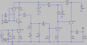
P.S. There is already a 46dB version based on that schematic posted for high out MC 1mV for RCruz back in the thread. If someone needs another gain, let me know.
salas said:
P.S. There is already a 46dB version based on that schematic posted for high out MC 1mV for RCruz back in the thread. If someone needs another gain, let me know.
Probably the same pcb can be used, just with different part values?
- Home
- Source & Line
- Analogue Source
- Simplistic NJFET RIAA