Here I am with another try. (In the hope I got the settings correct, not everything was clear to me and I am a bit in a rush—time's stolen)
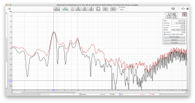
I measured the frequency with the tonearm/headshell unaltered, and made another with a 1.8 gr coin sticked onto the headshell. Couldn't go with much more...
3 variants were made:
while playing music, whith the needle sitting in the groove (TT not spinning), and with the needle "playing" the lead-out groove. (needle in the standing groove probably is useless...)
Red trace is the averaged (?) peak of one measurement.
I don't really know what to conclude of this... but it's really cool to realize I have something to learn with")
I measured the frequency with the tonearm/headshell unaltered, and made another with a 1.8 gr coin sticked onto the headshell. Couldn't go with much more...
3 variants were made:
while playing music, whith the needle sitting in the groove (TT not spinning), and with the needle "playing" the lead-out groove. (needle in the standing groove probably is useless...)
Red trace is the averaged (?) peak of one measurement.
I don't really know what to conclude of this... but it's really cool to realize I have something to learn with
Attachments
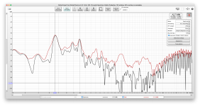
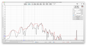
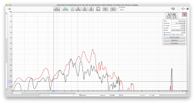
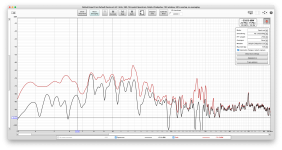
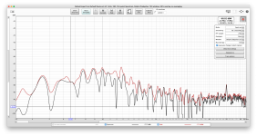
Between spinning music and standing noise graphs its the 6.6Hz poking out in music both in real time and peak memory black & red. Little coin mass on headshell seems to be taming the 20-30Hz area peaking and hightening the main resonances. The spinning inner groove is inconclusive about the 6-7Hz area as it looks not excited for lateral resonance but damped.
Ties with the 6.6Hz first two graphs peaks. ~13Hz peaks are there too but better seen in the second inner and first standing graphs red curves. Could be the vertical resonance excited a little. Even so by some room noise in the standing case. The 50Hz hum is also exposed in the last four graphs but looks low enough.OTOH, this Polk-Calculation-Service suggests a peak around 6-7 Hz...
Just installed something worthy of the UFSP.
No reviews in the internet from what I know.
A big thanks to Salas for the amazing electronics and effort.
Just heard the first track and need some more listening to write a review. But it's magic all over..

No reviews in the internet from what I know.
A big thanks to Salas for the amazing electronics and effort.
Just heard the first track and need some more listening to write a review. But it's magic all over..
Hello all,
Its good to see this thread going strong.
Back in Jan 2018 I built the Simplistic NJFET RIAA pre using the mini kit and boards purchased from Mr Tea-bag. I completed the kit using 30v secondary's (see post #16902, page 846), and other normal parts I had at hand.
It all went together great and it set up with no problems. I used an old cassette deck case for the audio boards (shelf 2 below) and separate case for the raw PSU (shelf 3).

My intention was to put it into a decent case at a later date.
Fast forward 5 1/2 years and I still using it like that, - so I reckon its about time I finished the project properly.
Here's what i'd like to do, and would greatly appreciate your help:-
Any recommendations or advice would be gratefully appreciated.

Kind regards
Roy.
P.S. Could you point me to a picture of the PCB please? I'm finding it rather difficult to identify some specific components on the board as the labels are obscured by components.
Its good to see this thread going strong.
Back in Jan 2018 I built the Simplistic NJFET RIAA pre using the mini kit and boards purchased from Mr Tea-bag. I completed the kit using 30v secondary's (see post #16902, page 846), and other normal parts I had at hand.
It all went together great and it set up with no problems. I used an old cassette deck case for the audio boards (shelf 2 below) and separate case for the raw PSU (shelf 3).
My intention was to put it into a decent case at a later date.
Fast forward 5 1/2 years and I still using it like that, - so I reckon its about time I finished the project properly.
Here's what i'd like to do, and would greatly appreciate your help:-
1. Find quality matching enclosures to fit the boards into
2. Source and fit quality components where they're thought to be most beneficial.
I'm thinking Resistors R1, R14 and Capacitors C3, C4 plus any others you feel would benefit.
I also want to make a new umbilical using 4 core screened cable with cannon connector and fit new quality phono sockets.Any recommendations or advice would be gratefully appreciated.
Kind regards
Roy.
P.S. Could you point me to a picture of the PCB please? I'm finding it rather difficult to identify some specific components on the board as the labels are obscured by components.
Hello Roy,
Nice that you kept it since 2018 and still happy enough with it to encase it better. For R1 R14 put Z-Foil if you can. For C3 C4 consider ClarityCap. Made in Britain and offering few ranges to choose from. Here's a components side render of the FSP version you asked for.
 components placement.jpg")
(Ignore the tiny + marks on the designations, they are for the software).
Nice that you kept it since 2018 and still happy enough with it to encase it better. For R1 R14 put Z-Foil if you can. For C3 C4 consider ClarityCap. Made in Britain and offering few ranges to choose from. Here's a components side render of the FSP version you asked for.
(Ignore the tiny + marks on the designations, they are for the software).
For the regulator sections no matching semis care. The hfe ranges are 3xx-40 and 5xx-C for the BC types. The PF5102 JFETs won't differ widely in bias Id because there are high value enough degeneration resistors for them in the circuit. If you have many use between 8-10mA Idss. Only watch how you handle the power Mosfets because their gates are sensitive to static discharge. Not talking about antistatic wriststrap, special bench mat, lab coat and dust free INTEL style measures. Just don't shuffle your feet on a carpet and use a grounded soldering iron. Last but not least don't stroke the house cat while soldering
I 've been very busy lately, but here is some report. Both UFSP units and their power supplies are ready. One unit went to a very close friend who reported that it's "impeccable" and the other one keeps me company as I type this post. In the original guide of FSP there is a suggestion to connect the shield of the power supply dc cord to one channel 0 point in the raw PSU. This did not work well for me, producing some buzz. I went the other way around, connecting the shield in the umbilical end that goes to the phono and cut it at the other side. Other than that everything works fine and fine is probably an understatement. My greatest thanks to Salas, Teabag and everyone here!
"Connect the umbilical cable's shield only at one raw PSU's 0 point, cut its other shield end off" was the original phrase i.e. the shield to be grounded but not connecting the two boxes.In the original guide of FSP there is a suggestion to connect the shield of the power supply dc cord to one channel 0 point in the raw PSU. This did not work well for me, producing some buzz. I went the other way around, connecting the shield in the umbilical end that goes to the phono and cut it at the other side.
Yes, it was in one side only in the first try, just as the guide suggested, but for some reason I had some buzz in that channel (in really high volume, far away from my max listening volume). Anyway, after all it's super clean now, just reported it if anybody faces something similar to try it the other way too. The shield now goes to the same place with the turntable ground on the phono pcb, but I am not sure if I have a path to the PSU ground that way.
Maybe there's an extra path through interconnects of other equipment in the system. In any case your umbilical cord's shield still is one way connected regarding the two boxes. Whatever suites a system best. There are application specifics always. You do have return paths in the umbilical from Ubib1.3S to raw psu. One zero line wire for each channel. They see the 1Ω/10Ω loop breaking resistors to the psu box/mains protective earth. You did well to report an alternative. Could prove useful to another builder.
For the regulator sections no matching semis care. The hfe ranges are 3xx-40 and 5xx-C for the BC types. The PF5102 JFETs won't differ widely in bias Id because there are high value enough degeneration resistors for them in the circuit. If you have many use between 8-10mA Idss. Only watch how you handle the power Mosfets because their gates are sensitive to static discharge. Not talking about antistatic wriststrap, bench mat, lab coat and dust free INTEL style measures. Just don't shuffle your feet on a carpet and use a grounded soldering iron. Last but not least don't stroke the house cat while soldering
I got only six pf5102. Measured the Idss, but they seem quiet different;
536
554
605
757
890
1020
Is this fine to use for the regulator? Or do i have to order some additional?
- Home
- Source & Line
- Analogue Source
- Simplistic NJFET RIAA