Hi Rick (and Salas)I swear they are in the correct holes. Remember I was able to get the proper bias voltage initially. My rail/ground was low and that is when I placed the resistor in series with the WRONG resistor and created this BIG problem in an attempt to solve a little problem, damnit.
I did measure across the outer pins. I have those hook type measuring leads so they were firmly attached to the leads and no chance of them shorting. I attached the leads before turning on the amplifier. I let it fully warm up (20 minutes) to see if anything changed. It did start out higher - 0.76 and then settled down to 0.73.
Do you think I should replace this "970" with the BC560 and see what happens?
This one will be a simple swap (respecting the different holes for placement).
I am starting to wonder if the "369"'s are the problem. Any chance of that?
Thanks very much for your time and trouble,
I'm having same problem as you describe in your post (8 years ago
") ). I only measure 0.78V across TP1 and TP2. Did you ever solve this issue? I have been looking for the ansver, but I'm drowning in posts.
). I only measure 0.78V across TP1 and TP2. Did you ever solve this issue? I have been looking for the ansver, but I'm drowning in posts.Here is my status:
I belive I have the the first or some early version of the PCB's. I forgot about them, and have just finnished them.
1 board works or at least it measures correctly.
The other board has issues:
The 4 leds are very slowly turning on, and are more dimmed than the same 4 leds on the working board.
Raw PSU voltage is about 55V. I read somewhere that a 20omh resistor in series with the PSU output could bring the voltage down to a save level. So that is implemented, and the Voltage is now about 50V.
The Rail voltage is 30-31V max. I know R3x can be increased to get more rail voltage, but I'm not sure this is the culprit.
Voltage across TP1 TP2 is 0.78V and doesn.t change.
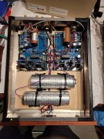
I have attached a picture of my build.
Any sugestions are much apreciated.
Regard
Mikkel
Attachments
Hi
Lets see.. First move the black film capacitors so to have one leg in the pad next to R5x.
The way they sit now across Vout without resistor damping there might be some rail oscillation.
Then check for about same voltage drop between two legs of each R1x CCS current setting resistor (brown Dale CPF) in both shunt regulators. CCSmA=Vdrop/15R. Around 100mA is correct. Is also the temperature comparable between the good and faulty channel corresponding sinks?
If the CCS current is there while both MOSFETs warm up and the shunt reg adjusts Vout freely when turning VR2x, the rail feed basically works. Your now max Vout might be enough or not and R3x can be increased. VR1 helps too. But before going for R3x, see if the DC voltage between Q3 BJT's base pin and general ground is comparable between channels. Voltage drop across R13 in both channels should be comparable too if Q7 feeds comparable current in both channels LEDs quad as well.
For what gain chosen make sure the proper active and passive configuration parts are inserted in same places and values between channels.
The above checks should give us a clue about the problem area or at least eliminate some initial possibilities. Let us know.
*The 20R for raw PSU drop is to be located between its diodes bridge +out and reservoir capacitor, not on its final voltage output.
*The wire extensions for the off-board C4 may attract hum or degrade sonics with their inductance. Better a capacitor that fits.
This Jensen has huge 20uF value for the purpose. A nice 2-4.7uF smaller type is enough for 20kΩ-10kΩ next stage input impedance.
Almost done, power supply in box and all wired up, preamp box only needs XLR plug from power supply wired up. Signal wires and drill holes for M1 and M2.
Have tested power supply previously. I will retest, then connect to phone preamp.
Phono box does not yet have the jumpers installed to bring power from shunt regulators to phono boards, can I fire up like this and measure shunt boards out put without being hooked to phono board? With no other load?
Final question, had this info, but new computer and new phone lots of info from before lost,
What is final fire up protocol? I remember having to adjust T something to 4 volts...
Thanks in advance,
Russellc
Russellc
I tested my Shunt Regulator before I soldered power wires to Signal Board. I am not at the house while I write this but I will give you an idea of the voltages to look for.
34 volts into Raw Power Supply
44 volts out of Raw Power Supply
use variable trimmer pot on Shunt Reg and set 31 to 33 volts. Test at “V+ & G” on Shunt Reg.
Hook power to Signal Board, use variable trimmer pot on Signal Board to set 4.0 volts at the”+ & -“ Test Points on bottom edge of Signal Board
To get 4.0 volts at the Test Points on the Signal Board you may have to raise or lower voltage on the Shunt Reg. The reason the Shunt Reg voltage may have to be adjusted up or down is because you may run out of travel “clicks will be audible” on the trimmer pot on the Signal Board.
I plan to get my power supply and Phono Pre into the enclosures this week, I am excited
Good catch Salas, I missed that point in my post to Russellc.But set the sensitivity choice on the DIP switches before powering the phono to adjust the Test Point. Each sensitivity setting is normal to vary in optimum rail voltage value for 4V T.P.
I have my DIP switches set at 47k load and 40 dB sensitivity
Thanks
Hi SalasHi
Lets see.. First move the black film capacitors so to have one leg in the pad next to R5x.
The way they sit now across Vout without resistor damping there might be some rail oscillation.
Then check for about same voltage drop between two legs of each R1x CCS current setting resistor (brown Dale CPF) in both shunt regulators. CCSmA=Vdrop/15R. Around 100mA is correct. Is also the temperature comparable between the good and faulty channel corresponding sinks?
If the CCS current is there while both MOSFETs warm up and the shunt reg adjusts Vout freely when turning VR2x, the rail feed basically works. Your now max Vout might be enough or not and R3x can be increased. VR1 helps too. But before going for R3x, see if the DC voltage between Q3 BJT's base pin and general ground is comparable between channels. Voltage drop across R13 in both channels should be comparable too if Q7 feeds comparable current in both channels LEDs quad as well.
For what gain chosen make sure the proper active and passive configuration parts are inserted in same places and values between channels.
The above checks should give us a clue about the problem area or at least eliminate some initial possibilities. Let us know.
*The 20R for raw PSU drop is to be located between its diodes bridge +out and reservoir capacitor, not on its final voltage output.
*The wire extensions for the off-board C4 may attract hum or degrade sonics with their inductance. Better a capacitor that fits.
This Jensen has huge 20uF value for the purpose. A nice 2-4.7uF smaller type is enough for 20kΩ-10kΩ next stage input impedance.
Thank you for your input. I will have a look at it, asap.
Mikkel
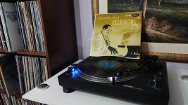
A little story about my ufsp, my nagaoka cart and some old speakers: few days ago I bought a pair of old Arcus TM55 2-way speakers to replace my rotten TM65 3-way speakers. At first I was annoyed after I hooked them up. The midrange sounded somehow recessed, the high end sounded sharp and sibilant compared to the old set of speakers.
Today I thought "let's check the sources" and I had a look at how I configued my phono setup. I searched about how to load the Nagaoka MP110. And I found that it has a rather high inductance of 810mH. I found an old review by TNTaudio of the older MP11 cart that is supposed to be identical with the MP110. The review states that a lowish input capacitance can lead to a recessed midrange.

So I took the C2y caps and hooked up 150pf to the inputs of my UFSP. I also changed the input impedance from 47k to 53k. After that I re-adjusted the cart on the headshell using a Technics sl1200 Baerwald protractor provided by vinylengine.
The difference was HUGE. The midrange response was way better then before, without any fatiguing, shouty mids that my old speakers used to throw at me. The balance in the music is astonishing. I also have less sibilant highs then before, but I was able to hear more details then ever. The sound is both bold and airy, in a positive way. The soundstage also improved big time. I found myself listening to records for more then 6 hours.
Conclusion: my "new" 2-way speakers are a blast. But I wouldn't have realised that if I had not optimised the loading and alignment of my MM phono cartridge. Hope this is not considered off topic here 😃
Today I thought "let's check the sources" and I had a look at how I configued my phono setup. I searched about how to load the Nagaoka MP110. And I found that it has a rather high inductance of 810mH. I found an old review by TNTaudio of the older MP11 cart that is supposed to be identical with the MP110. The review states that a lowish input capacitance can lead to a recessed midrange.
So I took the C2y caps and hooked up 150pf to the inputs of my UFSP. I also changed the input impedance from 47k to 53k. After that I re-adjusted the cart on the headshell using a Technics sl1200 Baerwald protractor provided by vinylengine.
The difference was HUGE. The midrange response was way better then before, without any fatiguing, shouty mids that my old speakers used to throw at me. The balance in the music is astonishing. I also have less sibilant highs then before, but I was able to hear more details then ever. The sound is both bold and airy, in a positive way. The soundstage also improved big time. I found myself listening to records for more then 6 hours.
Conclusion: my "new" 2-way speakers are a blast. But I wouldn't have realised that if I had not optimised the loading and alignment of my MM phono cartridge. Hope this is not considered off topic here 😃
Thanks, I remembered having to set the voltage, but not the order, and couldn't remember if shunt regulator could be fired up not connected to boards, and you answered that.Russellc
I tested my Shunt Regulator before I soldered power wires to Signal Board. I am not at the house while I write this but I will give you an idea of the voltages to look for.
34 volts into Raw Power Supply
44 volts out of Raw Power Supply
use variable trimmer pot on Shunt Reg and set 31 to 33 volts. Test at “V+ & G” on Shunt Reg.
Hook power to Signal Board, use variable trimmer pot on Signal Board to set 4.0 volts at the”+ & -“ Test Points on bottom edge of Signal Board
To get 4.0 volts at the Test Points on the Signal Board you may have to raise or lower voltage on the Shunt Reg. The reason the Shunt Reg voltage may have to be adjusted up or down is because you may run out of travel “clicks will be audible” on the trimmer pot on the Signal Board.
I plan to get my power supply and Phono Pre into the enclosures this week, I am excited
I only have to drill the holes for M1 and M2, and a little amp box wiring.
Russellc
Not out of topic at all! I many times advocated here to search out optimum resistive and capacitive loading for MMs. Especially when they manifest weird tonal clues. Congratulations for your tuning efforts. A very practical example.Conclusion: my "new" 2-way speakers are a blast. But I wouldn't have realised that if I had not optimised the loading and alignment of my MM phono cartridge. Hope this is not considered off topic here 😃
Hi SalasHi
Lets see.. First move the black film capacitors so to have one leg in the pad next to R5x.
The way they sit now across Vout without resistor damping there might be some rail oscillation.
Then check for about same voltage drop between two legs of each R1x CCS current setting resistor (brown Dale CPF) in both shunt regulators. CCSmA=Vdrop/15R. Around 100mA is correct. Is also the temperature comparable between the good and faulty channel corresponding sinks?
If the CCS current is there while both MOSFETs warm up and the shunt reg adjusts Vout freely when turning VR2x, the rail feed basically works. Your now max Vout might be enough or not and R3x can be increased. VR1 helps too. But before going for R3x, see if the DC voltage between Q3 BJT's base pin and general ground is comparable between channels. Voltage drop across R13 in both channels should be comparable too if Q7 feeds comparable current in both channels LEDs quad as well.
For what gain chosen make sure the proper active and passive configuration parts are inserted in same places and values between channels.
The above checks should give us a clue about the problem area or at least eliminate some initial possibilities. Let us know.
*The 20R for raw PSU drop is to be located between its diodes bridge +out and reservoir capacitor, not on its final voltage output.
*The wire extensions for the off-board C4 may attract hum or degrade sonics with their inductance. Better a capacitor that fits.
This Jensen has huge 20uF value for the purpose. A nice 2-4.7uF smaller type is enough for 20kΩ-10kΩ next stage input impedance.
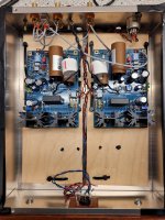
I found the problem! Q3 was in the Q3z position rather than the Q3y position. I wonder who put it there 🤔😜
Now everything measures as it is supposed to. Next step is hooking it up to the stereo. Can't wait 😊
I followed your other suggestions:
Moved 20R to RD/link.
Moved the film cap closer to R5x
Change the output cap to 2.2uf so that it fit onto pcb. Question: can the value of the output cap be too big? I had the 22uf laying around, and thought I would give them a try.
Regards Mikkel
Attachments
Now it's good 
About the output capacitor's value, its not really written in stone, most of the subsonic cut curve is shaped from the previous 0.1uF coupling.
But the output cap completes it. In combination with the line stage's input impedance.
Smaller bass reflex speakers because not deeply tuned don't have enough VLF port resistance to control the cone. Imperfect arm cart resonance or a somewhat feedback prone turntable installation can promote that further etc.
In other words, you can use a higher value but judge in the context of your system. Keeping subsonic control. Test and see.
But let us know how you liked it as it is in your last picture first. With what cart and turntable etc.
- Home
- Source & Line
- Analogue Source
- Simplistic NJFET RIAA