There are the shunt regulators in-between helping but high frequency switching noise can still couple on the PCB tracks and signal wiring like AM radio or spread through the ground.
If you will hear relatively thin sound its a negative clue when not having the linear raw PSU to directly compare tone and hiss level.
If you will hear relatively thin sound its a negative clue when not having the linear raw PSU to directly compare tone and hiss level.
Hi all,
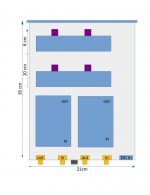
limited space makes it necessary to employ max a 23cm width case. Wondering if the layout below is good enough heat wise for the shunt UBiBs. Distance between the first UBiB transistors and the second UBiB will be about 4 cm. There is space for more distance if necessary. The transistors will be chassis mounted.
Thanks!
Attachments
Being lazy as I am, although I am sure I 've read a response regarding this one, I will abuse you kindness and ask again (ok, I 've searched about 50 pages so far and could not find it):
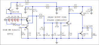
Regarding R5-R6 when not using the PRP resistor 6.77k, what's the value we are aiming for? For example 1.5M with 6.8k is closer to 6.77k than 1M and 6.8. Or am I just overthinking this?
Regarding R5-R6 when not using the PRP resistor 6.77k, what's the value we are aiming for? For example 1.5M with 6.8k is closer to 6.77k than 1M and 6.8. Or am I just overthinking this?
1M//6.8k=6.75k original combination has 0.0155dB more curve undulation than 6.77k in simulation when values are perfect and I don't think its critical but you can also use 1.5M//6.8k=6.769k. No problem. I most probably did not have 1.5M in my spares when I built the first circuits. Or the parts and meter tolerances were favorable to 1M.
 , it obviously doesn't make any real world difference. Thanks for the quick response.
Hi Salas. I am using the MM version of the folded simplistic...when I built it I was using MM cartridges (2M bronze). I power it with the 1st generation BIB shunt reg.
But now I am using MC cartridges with this same phono stage. Using your Jfet step up from the simplistic PDF powered by batteries for MC use.
Is it worth building a new simplistic with the MC capability in one unit? Will I see any performance advantage vs the MM simplistic + Jfet step up?
But now I am using MC cartridges with this same phono stage. Using your Jfet step up from the simplistic PDF powered by batteries for MC use.
Is it worth building a new simplistic with the MC capability in one unit? Will I see any performance advantage vs the MM simplistic + Jfet step up?
Attachments
You delete a stage and a capacitor coupling when losing the pre-pre step up so you should expect some increase in transparency. Maybe not spectacular because such low level input stages don't produce much signature THD, but it should be an audible circuit simplification. Remember, absolute phase also returns to correct after that (3 vs 2 gain stages reversing).
You delete a stage and a capacitor coupling when losing the pre-pre step up so you should expect some increase in transparency. Maybe not spectacular because such low level input stages don't produce much signature THD, but it should be an audible circuit simplification. Remember, absolute phase also returns to correct after that (3 vs 2 gain stages reversing).
Thanks Salas. Good insight.
What did you all use for the ground binding post hardware?
Look at this part: 552-0600 WHT Deltron | Mouser
Look at this part: 552-0600 WHT Deltron | Mouser
Hi Dudeisms,
I use this one. Very high quality.
Cardas Connector ACBP-S Cardas Ground Post
Last edited:
I forgot to mention… it is easy to set it as insulated from enclosure if needed. My enclosure is connected to Earth Ground, but TT ground connected to Folded signal ground via that insulated from box post.
Thanks Salas. Good insight.
BTW regarding absolute phase in a three gain stages inverting system, like you now got with an active pre-pre, reversing the cartridge pins wiring can restore it. With exception of some cartridges having connected one channel's earth pin to the cartridge body as a shield. Was usual in vintage MM models.
Not that you can easily tell a difference with typical recordings and non linear phase speakers, maybe on headphones with some minimalist recordings. If there was provision to keep them phase consistent during program production, cut, and press. Else they will like it by chance.
Not silly at all. You can insulate that post and connect to chassis at a single point via a wire, or you can use the post itself as the single connection to ground.
There is no single right answer, but remember that ground touches chassis once, and once only.
I totally agree with 6L6 and it is not one way that it is suitable for all of us. You TT might be grounded to safety Earth and my is not, and etc… I tortured Salas once a lot about GND connection for my Folded and for other builds till I found my GND loops and fixed the mess. Many members tried several configurations and they ended up with what is sounded quieter to them (plus “safety first”).
About my case (me only), I connected my tonearm GND to insulated Cardas post and it is connected to Folded PCB GND pads. That GND is signal GND and it is elevated by 1R for left and 1R for right plus 10R (Raw DC PCB) from safety Earth in PSU box. Folded enclosure is connected to safety Earth via extra wire running through my umbilical cord and it is connected to PSU enclosure. PSU enclosure is connected to safety Earth in the same point as signal GND is connected (star). Some guys connected TT GND to Folded via not insulated GND post and no safety Earth for that box. Hope it is helpful.
Hello everyone, I've taken great interest into this phono project.
Does anyone still have a set of Jfets they can sell me for this phono stage.
it was sold as a group buy a while ago. I'm stuck looking for the correct ones needed for reasons everyone knows.
Thanks in Advance
Does anyone still have a set of Jfets they can sell me for this phono stage.
it was sold as a group buy a while ago. I'm stuck looking for the correct ones needed for reasons everyone knows.
Thanks in Advance
- Home
- Source & Line
- Analogue Source
- Simplistic NJFET RIAA