He should try Raw board's PE connected to PSU chassis and the umbilical cable's shield one end connected to PSU chassis. The shield's other end left alone not connected to the main chassis. Use no other chassis to chassis wire. Its also no big deal if the umbilical has no shield. PE Raw is safety ground lifted already via two fat diodes and a fat resistor on that board.
Folks:
I've made the revisions suggested by Tea-Bag and Salas: the PE via on the RAW power supply pcb is now connected to the PS chassis (and toroid shield) and earth ground. The ground wire between the PS chassis and UFSP chassis has been disconnected.
The hum is unchanged. What would you suggest as a next step?
Regards,
Scott
Salas & Co.:
The power supply chassis is about 25-30 cm from the UFSP chassis. The turntable has a 2-prong cord and is plugged into an SG-4 sine wave generator (a speed controller). The SG-4 has a 3-prong cord and is plugged into a power distribution box. The two pairs of RCA interconnects leading to the UFSP (from the turntable and to the preamplifier) are both shielded with the shields connected at one end only.
The hum persists regardless of whether a ground wire connects the UFSP chassis to an earth ground connection.
Any and all advice appreciated.
Regards,
Scott
The hum persists regardless of whether a ground wire connects the UFSP chassis to an earth ground connection.
Any and all advice appreciated.
Regards,
Scott
Is the hum present with only one RCA connected from the TT?
Rush
Try connect the speed controller box to the TT ground lug on the phono box with an alligator lead. To see if it makes any difference.
Salas:
I was wrong about there being a 2-prong cable on the turntable; it is 3-prongs. However, the earth ground for the turntable power receptacle in the SG-4 was disconnected (the SG-4's power inlet's ground was still connected to the SG-4 chassis). I reconnected the ground connection in the SG-4 and, as a separate test, ran a wire from a ground lug in the SG-4 to the turntable's ground lug. There was no difference in the hum with either or both ground connections.
Is the hum present with only one RCA connected from the TT?
Rush:
Yes. The hum is present in both channels at an equal volume when both RCAs are connected to the turntable. When the right channel RCA cable is removed, the hum is unchanged in volume and is still present in both channels. When the left channel RCA cable is removed, the hum remained in both channels and increased slightly in volume.
Regards,
Scott
The two pairs of RCA interconnects leading to the UFSP (from the turntable and to the preamplifier) are both shielded with the shields connected at one end only.
Try a regular RCA cable with shields connected at both ends. (Or have I misunderstood you? Is there a return conductor in the RCA cable besides the shield?)
Folks:
Could the hum be caused by a broken headshell lead? I suspect there may be an issue with the right channel hot wire.
Regards,
Scott
I had a headshell lead disconnected a few weeks ago when hooking up a headshell to my tonearm. It buzzed a lot, it was not subtle.
One could i guess take some small pliers or tweezers and connect with some effort to see if the hum drops down.
If you are saying with TT disconnected, no hum, then we are left assuming that the TT has some grounding issue somewhere?
headshell/tonearm lead wire issues do not sound fun.
Tea-Bag:
Yup, I think the problem has been isolated to the turntable's right channel. Time to start looking at options. The tonearm on my Apollo is air bearing, so the wires are particularly small gauge and insulated just with varnish; wire drag can really affect an air bearing's performance.
Thanks to everyone who helped me figure out what was not the problem. And I'm sorry to have distracted the focus of this thread from Salas' stellar phono stage.
Regards,
Scott
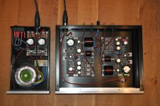
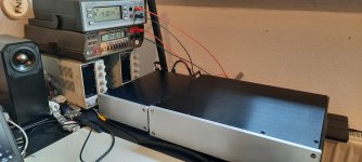
Hi Salas (thanks for reminding me to write something more here) and all...
adjusting 4V was time consuming, but fun. Enough time while working in home office.
Both meters are "calibrated" by me, at least adjusted to show the same value, differing about 4 digits at 20V, at 4V about 1 digit.
So adjusting both voltages to 4V (beginning now at 4.2xxV with turning on and decreasing to 4.00x V after about 3 hours, staying there.
Then the shock while trying to evaluate the value for C2y. Connected to my Technics 1210 and Denon amp, listening with headphones.
HUMMM... Grrr. Short story: The terminal for the ground connection is crap. No connection, regardless how tight the screw is..
Installed a new one, now silence. Phew.
To the next step: Started wit 150 pF, listening, inserting 220 pF, ..., at 390 pF I thought, man, when will it sound more bright? It's not getting there...
Ok, when you don't hear what you want to hear, it's not easy..
Once I saw that I mixed things up I heard what I wanted to hear. 100 pF sounded too bright now, 150 a little bit, 220 about, maybe, ok, this is what most of the others chose, so, I should hear now that it's fine...
No, not really, I had Pink Floyds "Division Bell" on Vinyl and CD for comparison. But then I settled also for 220 pF.
That's the current state of installing the phono pre.
Ordered some decals for labelling the front plates.
Good night,
Ulf
Attachments
Salas, i have a problem with the leds
Tea has send to me the leds with vm :
1,774,
1,776
1,779
1,779
1,779
1,780
1,781
1,781
1,782
1,783
1,785
1,786
1,786
1,787
1,802
I know for the 4s is 7,2V and for 3s 5V
there is no way to achieve the voltage
Maybe to alter with other leds?
Thank you in advance
PS I have for now the cartridge VDH Crimson Stradivarious
@ Ulf
Your build reacts "by the book" both in adjustment and HF trim cap choice. Confidently indicating no construction mistakes. For 4V TP don't obsess too much, don't mind some little drift as it is natural. One tenth of a Volt similarity in drift behavior would already be very good and you have done a much finer job. For trimming HF response the C2Y cap options are there to can compensate bright or dull system tendencies. Which stick out easier with vinyl rigs even due to geometry choices like VTA. When trying within fairly neutral cartridge and speakers circumstances most people do report the 220pF choice indeed.
Your build reacts "by the book" both in adjustment and HF trim cap choice. Confidently indicating no construction mistakes. For 4V TP don't obsess too much, don't mind some little drift as it is natural. One tenth of a Volt similarity in drift behavior would already be very good and you have done a much finer job. For trimming HF response the C2Y cap options are there to can compensate bright or dull system tendencies. Which stick out easier with vinyl rigs even due to geometry choices like VTA. When trying within fairly neutral cartridge and speakers circumstances most people do report the 220pF choice indeed.
@ Oracle
Those VFs you listed are fairly consistent as Leds go. They are not hand matched, just coming from a tight enough tolerance type. I have seen more apart VFs. When those figures are taken with a DMM in diode check mode very little current is used to save its battery. They naturally show more VF if tested at 5mA for the phono and 2mA for the shunt reg PSU.
Hitting an absolute 4xVF figure goal in the channels is not optimizing the circuit by the way, because its just a ballpark indicator for the cascode's voltage bias.
Put together Led groups of about equal total Vf between channels when selecting from those you got. Matching between channels what figure can be actually reached is the more productive way when willing to go into VF detail.
In the 1.3S shunt regs its not worth the effort to get Leds very close. They only drop enough voltage for protecting a certain JFET's max spec there.
- Home
- Source & Line
- Analogue Source
- Simplistic NJFET RIAA