Hello guys, I need some help in troubleshooting in my 2015 FSP.
I have done the below and my analysis.
Please let me know on any other suggestions on where to check? Or possibility on other problems?
Only Q1 is populated, aiming for ~57db gain
Ch1
Only d1-4 no light
Q7 ds resistance is 17ohm
Q3x & Q5x, ds resistance is 77ohm
Q4x vbe is 0.79
Rail and input dc is 44v & 38v.
Between Tp1 & tp2 is -0.07v
- Suspect K117 at Q7 is gone, thus D1-4 not lighted and thus cannot bias and seeing TP1/2 voltage above.
Puzzling ch2
Input 51v
Rail is 22v, cannot be adjusted via VR2x
All leds lights
Bias between Tp 1 & tp2 can adjust to 3-4 via VR2x and VR1
Q3x & Q5x, ds resistance is 15ohm
Q4x vbe is 0.79
Q1x warmer than q6x
- Suspect K117 at Q3x & Q5x is gone thus Rail voltage got stuck.
Ch1 Q7 most likely gone or there is some problem at its solder joints. Q3x Q5x measured at 77 Ohm RDS is reasonable.
Ch2 Q3x Q5x suspects yes, remove them to confirm RDS & IDSS, but before that see if Q6x is the reason. Measure its VDS. 3-4 VDC is normal. Confirm R3x's value also.
Ch2 Q3x Q5x suspects yes, remove them to confirm RDS & IDSS, but before that see if Q6x is the reason. Measure its VDS. 3-4 VDC is normal. Confirm R3x's value also.
being at one of those so simple steps, not seeing the solution...
Hi again
I am anxious I could bungle the connection of my trannies to the raw PSU...
I have two TTSA0030 Audiograde 2 x 16V 30VA to connect. They're dual secondaries.
I connect them in series, right? Anything I should take special care of (like, polarity)?
Has anyone a sketch/foto/schematic available onto which I could have a peek?
Thanks, and happy weekend!
david
Last edited:
Connect the second with the third wire of the four secondary ones. The first and fourth free remaining wires are the new summed secondary ends.
For example a label states SEC 1 are the red & black wires, SEC 2 are the yellow & orange wires. You tie together black & yellow. The free remaining red & orange are your new series secondary with double the voltage.
For example a label states SEC 1 are the red & black wires, SEC 2 are the yellow & orange wires. You tie together black & yellow. The free remaining red & orange are your new series secondary with double the voltage.
The yellow green should be the internal static screen drain wire.
[emoji1317]
Ah, perfect!
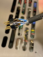
So 1 white + 1 brown go together, the other to the psu...
They still need to be in series and that is tricky with same coloured secondary's. Connect a brown and white together and measure the output voltage before connecting to the power supply. If you get 2 X the secondary AC voltage you are good. If you see less or very little AC then change just 1 of either the brown or white to get them in series.
Last edited:
They still need to be in series and that is tricky with same coloured secondary's. Connect a brown and white together and measure the output voltage before connecting to the power supply. If you get 2 X the secondary AC voltage you are good. If you see less or very little AC then change just 1 of either the brown or white to get them in series.
Thank you, TUM!
I did so and the results are weird:
I connect the inner secondaries (orange-grey) and get 0.003v
I connect two outer secondaries (orange-grey) and get 0.0v
...
Faulty dmm or anything else?


One of the arrangements should have given you the 32 volts. I'm sure you would have set the meter to AC volts but just confirming?


I guess I‘ll have to RTFM my meter.
The other not so smart one had me decide what current to use et voila!
")
- Home
- Source & Line
- Analogue Source
- Simplistic NJFET RIAA