No, the ground is already routed through the Raw PCB as it should. Connect ground lines on both sides from RAW outputs to shunt reg PCBs. Connect the umbilical cable's shield at one chassis only. Also connect (bolt) mains protective earth to PSU chassis. Connect RAW PCB to PSU chassis only from where its labeled PE.
What board version? What cartridge? What DC voltages? Regulated rail voltages? If you mean the RAW supply voltages those are low. What is the transformer spec? Also post clear pictures of the boards. Top and bottom. Maybe we will spot something. If nothing is visually wrong next step is we will give you instructions to test some basic DC voltages around the circuit.
tribute,
This phono was build by me and set for MM or MC high gain. This was clearly mentioned in swap thread For Sale - Salas Phono Simplistic Preamp
I'll send you a pair of jfet's, but this will take some time, so please be patient.
Beside this, you will need to change R13 and populate R2 or R3. This is mentioned in documentation. When all parts are in place, you'll need to adjust again voltage between TP1 and TP2.
Regards,
Tibi
Last edited by a moderator:
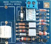
Hi, Here is a picture of the board I have, I believe they are from the 1st G/B.
DC voltage, from what I read from the .pdf set up instructions, it advised the DC voltages should be around 35VDC
''Use a DMM at DCV. Measure between RAIL+ and GND pads. Shall read somewhere between 34 & 36V''
I am measuring that voltage at the blue DC input wire clamps at the side of the phono boards.
The cart I am using is a Accuphase AC-2, this should I know be set up for the highest gain settings, but in the past have successfully ran it from a simple E/Bay phono amp with a published gain of 53dB.
Board on the left has muffled sounf, board on the right has no sound, just buzzing.
Cheers
Hi
Your cartridge is quoted 0.18mV output. Thus you should use the highest gain configuration (LMC) if for direct connection without step up transformer. http://www.accuphase.com/cat/ac-2en.pdf
You would have heard something weak but not wrong with your now insensitive configuration. But what you heard was very wrong. Which brings me to another point of stronger concern:
"I am measuring that voltage at the blue DC input wire clamps at the side of the phono boards."
Rail+ is a test point at the board near the trimmer as seen in your picture. For red probe. Diagonally nearby there is a convenient gnd test point for your black probe. Not to measure 34-36V between the screws of the blue DC in connector at the side. There you need higher DC level than on Rail+. About 45V is OK. Even 42V is enough. Without such DC relations no gain configuration will work correctly. Please let us know your transformer's spec and check its AC voltage output to the RAW DC board.
tribute,
This phono was build by me and set for MM or MC high gain. This was clearly mentioned in swap thread For Sale - Salas Phono Simplistic Preamp
I'll send you a pair of jfet's, but this will take some time, so please be patient.
Beside this, you will need to change R13 and populate R2 or R3. This is mentioned in documentation. When all parts are in place, you'll need to adjust again voltage between TP1 and TP2.
Regards,
Tibi
He will need to populate R2 AND R3 to suitable values regarding Q1 Q2 IDSS.
From the FSP (blue board) guide:
"Notes
2SK369BL. Select IDSS pairs for Q1, Q2. Test them in same ambient temp for long enough each so to settle. You may need a batch of 20pcs. Use corresponding resistor values for R2, R3 from this table:
IDSS mA 10 11 12 13 14 15 Tolerance 2%. How to measure
Rs Ohms 3.0 3.9 5.1 6.8 9.1 11 ~9mA through R2, R3 (each) is the expected bias.
Prefer matches from the 11-13mA range if you got, for better balance between current bias and source pin resistors noise."
So the two extra JFETs you will send him must be of comparable IDSS to those already installed along with four suitable chosen R2 R3 source resistors and two R13 1.2K 2W (parts total for two channels LMC). Test point voltage will have to be adjusted again in the end. But you mentioned some of that. I just state again as a summary.


Noted R13 (and R2) on a crop of your own picture. It should be 5.6k R13 with a 68R R2 when set for 43dB gain.
R13 2.2K 2W and few Ohm R2 (selected vs Q1 IDSS in the guide's table) gets you to 56dB gain normal MC (~0.5mV) sensitivity territory.
Both of those configurations work for a single 2SK369BL (Q1) as now installed. Always check/readjust test point after changes. Background hum shouldn't be unsolvable in your installation too with some experimentation. Because those assembled PCBs coming from Tibi were already performing adequately in his hi-fi system.
Try your SUT at 10X with an LMC cart as set for 43dB. But with 47k RL selection i.e. all DIP switches OFF. The transformer cartridge coupling could break a ground loop you may now have between TT and this phono system.
Attachments
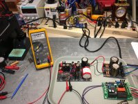
I finished the PCB's and tested the raw power supply and each channel PCB. Set rail to 34 vdc, with dip switches S5, S6, & S9 ON for LoMC, TP dialed in to 4.0 vdc on each board. Now to install the raw supply into the enclosure and making up the umbilical cable.
Slow progress in between preparing for winter at home.
Slow progress in between preparing for winter at home.
Attachments
- Home
- Source & Line
- Analogue Source
- Simplistic NJFET RIAA