Yes it is correct, the warmer they get the more current they draw. Not forever, their IDSS comes up a bit. So they steal from the load resistor's (R4) current branch and its voltage drop lessens (T.P). Its also correct that higher source resistor values degenerate more, so bias current and dissipation drops on those JFETs, and more local negative feedback happens. Because the voltage drops at work are antagonistic. Those events making them stabler in bias.
Alas, higher source resistance values add noise which is the enemy of LMC and MC modes. Because MC carts own resistance is in the same league of source resistors. They must be kept minimal thus Ibias also kept high for more transconductance. Two very desirable trends in those modes. For performance benefits the high gain modes are more exposed to temperature delta whims. But we have managed enough control and wide DC space for drift, allowing the builds to be workable and practical.
Alas, higher source resistance values add noise which is the enemy of LMC and MC modes. Because MC carts own resistance is in the same league of source resistors. They must be kept minimal thus Ibias also kept high for more transconductance. Two very desirable trends in those modes. For performance benefits the high gain modes are more exposed to temperature delta whims. But we have managed enough control and wide DC space for drift, allowing the builds to be workable and practical.
Thanks Salas for the details, Simplistic is a perfect name. I looked up the definition: treating complex issues and problems as if they were much simpler than they are! There are just a few components but there is a lot going on and it is a fine balance, just like a good recipe or wine.
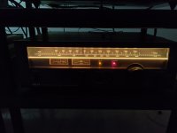
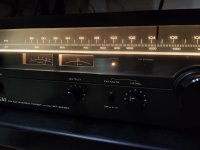
By the way I am happy because I scored an FM tuner from the late 70s that nobody had de-tuned or modified and all its lights and parts are original and working. An AKAI made in France. Weird thing that.
Just with four gang front end but brings full signal from a T wire dipole thrown on the floor. I am now listening again to old good analog FM stereo on a real system with it. Has warmth, strong staging, and sheer presence of body and drama in music. On good classical and Jazz transmissions you can listen for hours without fatigue. FM, tape, vinyl, are birds of a feather and flock together.
Just with four gang front end but brings full signal from a T wire dipole thrown on the floor. I am now listening again to old good analog FM stereo on a real system with it. Has warmth, strong staging, and sheer presence of body and drama in music. On good classical and Jazz transmissions you can listen for hours without fatigue. FM, tape, vinyl, are birds of a feather and flock together.
Attachments
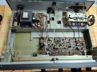
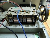
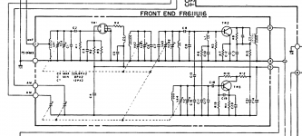

It has antenna gang, RF gang, RF second gang, local oscillator gang, and two AM gangs. Six sections. Considered as four gang FM.
It looks like one of the variable capacitor sections is acting as a preselector on the FM input - is that correct?
It looks like one of the variable capacitor sections is acting as a preselector on the FM input - is that correct?
Photo right to left first four discs section tunes the antenna to a booster using dual gate Mosfet TR1, next four discs filter the RF, another four discs sharpen that more, leftmost six discs tune the local oscillator TR2 that mixes output with the carrier at TR3 to produce the IF beat (intermediate frequency) to send downstream for detection. The two many sections groups with brown strap in between are for AM tune. The screws are TC (tuning cap) FM ant AM FM FM AM stages and in the hole at top mid-line left is TCo(scillator).
They used dual gate Mosfets back then in the better front ends. 3SK37 and alike. I have a friend who has a seven gang SONY ST-A6B which had been messed with before and it had low signal down to indication two. Also missing meter lights. He did recap to no result on signal and he tweaked the trimmer coils in the end to up the signal. It came up but who knows how it looks like on a swept signal IF bell curve test. Takes a ton of vintage lab gear to fully and surely align such beasts. Sounds good at least. And he recently located the missing fuse style lamps replacements.
By the way as I see in its service manual your SONY is four varicaps FM (three tune one local osc.) and has a good build. Four gang FM equivalent.
By the way as I see in its service manual your SONY is four varicaps FM (three tune one local osc.) and has a good build. Four gang FM equivalent.
Yes once the IF stages have been messed with it takes someone who really knows what they are doing and the right equipment to get things back. I've adjusted 455 kHz IFs on radio equipment but that is pretty basic compared to properly aligning a stereo FM receiver.
That is good info on the Sony, I haven't needed the service manual but I should get it - did you just google it? I did read that the audio opamp section in it could use some improvement.
Do you still have some good FM stations in Athens that don't compress/process to <MP3 quality?
That is good info on the Sony, I haven't needed the service manual but I should get it - did you just google it? I did read that the audio opamp section in it could use some improvement.
Do you still have some good FM stations in Athens that don't compress/process to <MP3 quality?
You will find the manual in hifiengine. Luckily there is a very nice extended ST-J60 scan. Has color and photos and schematics and PCB topography. My tuner's manual scan is a short dark mess for instance.
We have very few good stations surviving. Especially Radio 3 of the national broadcasting corporation is very natural sounding and has serious music program.
We have very few good stations surviving. Especially Radio 3 of the national broadcasting corporation is very natural sounding and has serious music program.
Phono is more useful than Tuner. There are only a couple stations worth listening, the national ERT as mentioned one of them.
The pirate FM stations, 35 years back, were far superior. Unfortunately while we can go back into vinyl somehow, we can't go back in those radio days, gone forever
The pirate FM stations, 35 years back, were far superior. Unfortunately while we can go back into vinyl somehow, we can't go back in those radio days, gone forever
I am really pleased to say that we still have some decent FM stations in Australia but of course there is great pressure for everything to move to DAB+ which in a vast country like Australia is just madness but governments are desperate to make money by selling off spectrum bandwidth so I suppose it is inevitable that ultimately we will lose our treasured FM stations.
Politicians, humph!
Politicians, humph!
@ savvas & graemed
Well spoken.
Its just about having fun while analog bands are still around. With 100 Euro range old tuner finds. Not an investment and it feels good. Vinyl will outlast FM the way it goes anyway. Who would have thought of that if you asked in the CD's advent years. About phono we are well enough equipped at least.
Hi Salas,
I have ordered Folded Simplistic Preamp from Tea-Bag along with Raw PSU and can’t wait to arrive and start populating it.
In mean time I have ordered remaining parts and few questions pops up.
As I have TT with 2 tone arms and cartridges, MC Benz Micro LPS 0.34mA and MM Nagaoka MP-200 4mA, reading build guide it states that in order to use Hi MC and MM cartridge Q2 and R3 should not be populated. Thant would leave me to choose whether I go for MC or MM.
The other day running trough hundreds of posts I stumbled on interesting one “18482” witch made me happy.
Basically you were stating that new version allows boards adjustment to any chart using only switches. Does it means that I can populate Q1 and Q2 regardless of cartridge and than adjust settings with DIP switches?
Another issue I have, I mistakenly ordered two 36VAC toroid transformers as I was following original guide and BOM for RAW PSU. Later I found out new RAW PSU uses 30 – 32VAC transformers.
Is there any issue if i keep 36VAC?
I apologies if above questions were already being asked and answered.
Thanks,
That's correct, you can have all gain modes set with just switches in the new UFSP realization. Yes it does mean you can populate both Q1 & Q2 regardless of cartridge.
Use 27R 3W for the two RD/Link positions in RAW PSU board. Those will drop down the rectified voltage under load adequately from your 36V already ordered transformers. We used to do that in the previous FSP blue board builds.
Please follow the schematics and gain set up info of post #17791 for the current UFSP build.
- Home
- Source & Line
- Analogue Source
- Simplistic NJFET RIAA