Little hiccup here. I’ve got one channel that is putting out excessive gain. While one channel tracks at all the settings, the other is way higher. at 40dB, the other is at 47dB. At 43dB setting, the other is at 51dB. At 56dB setting, the other is at 63dB.
All resistors were measured before install and appear to be identical across both channels.
I’ll pull it apart and take a closer look at the bad channel. It biases fine. Identical between channels.
All resistors were measured before install and appear to be identical across both channels.
I’ll pull it apart and take a closer look at the bad channel. It biases fine. Identical between channels.
So how about this craziness. On the channel with the appropriate gain, I actually soldered in Q4 backwards. R8 is 54R. I had measured my Q4 pairs at 9.4ma IDSS. Should I pull all the K170s and remeasure? I do have one more matched pair on hand here in case any went kaput.
I've been working on a case design using Protocase's software.
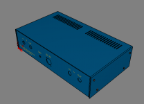
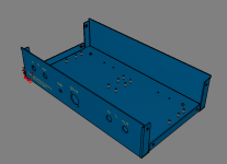
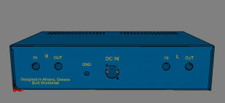
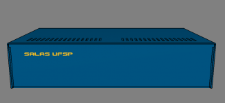
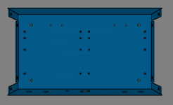
All the measurements and fastners are metric. Case is glossy powdercoat heavy gauge galvanneal steel (1.98mm/14 gauge). PEM standoffs are 8mm, screws are M3.
Price for a single unit is just a little more than a DL-103R. The price gets more reasonable in the 3~5 unit range. Here is the Protocase Designer file:
View attachment salas_ufsp_case.zip
Last edited:
Also see if R2 R3 are the same and what mV DC develops across them between channels in LoMC mode.
Thanks Salas -- I've been measuring voltage gain and converting it to dB. I've been feeding both channels 4 mv from an inverse RIAA (same one I used to measure the Itch). At 40dB setting, I'm getting .44v out on one channel and .64v out on the other (40.8dB vs 44dB).
In LOMC mode, that same 4 mv yields 5.46 volts on one channel (63 dB) and 7.38v on the other (65 dB).
R10 is 6.81K -- 24v drop across R10 in both channels.
R2-R3 are the same in both channels (3.9R provided by Tea). All 4 across both channels in LOMC mode are reading 33mv.
I keep poking around hoping to find something. The backwards installed Q4 measured fine, and I swapped it back in the right way -- channel working just as it did before.
The way it keeps repeating about the same dB difference with each sensitivity setting is systematic. Also the 65dB max is rather optimistic for this circuit but maybe its an experimental error. Must confirm the input mV accurately to say. Not of consideration though because we are after a channels match right now not absolute spec.
Is there a possibility some value is wrong in the passive RIAA components in one channel and exaggerates 1kHz test signal with a response hump?
Swap the test cables between channels also. Just in case something isn't gripping well. Have you got a scope? If yes compare 1kHz signals between channels R4s (T.P + - points will do) and Q4s drain pins (i.e. bottom of R10s) to GND for finding in which stage of the circuit the difference's source is.
It is fully BIASed and I’ll connect it to my Sonographe SG-3 with Bentz Micro cart today. I I’ll use my second DCG3 on its output. Will report soon.
Interesting American table. Not very usual.
The way it keeps repeating about the same dB difference with each sensitivity setting is systematic. Also the 65dB max is rather optimistic for this circuit but maybe its an experimental error. Must confirm the input mV accurately to say. Not of consideration though because we are after a channels match right now not absolute spec.
Is there a possibility some value is wrong in the passive RIAA components in one channel and exaggerates 1kHz test signal with a response hump?
Swap the test cables between channels also. Just in case something isn't gripping well. Have you got a scope? If yes compare 1kHz signals between channels R4s (T.P + - points will do) and Q4s drain pins (i.e. bottom of R10s) to GND for finding in which stage of the circuit the difference's source is.
Thanks Salas — already had tried swapping the inputs. Moreover, the RIAA is single input feeding two outputs, so they should always be identical.
I do have a scope — I’ll hook those points up to the scope and report back. Thanks!
Ok progress — I pulled out C2Y from both channels and output voltage dropped from the weird channel to match the other. The weird channel jumped up once while measuring, but I’ll keep and eye on it. I’m wondering if there is also a bad solder joint somewhere. Also will measure that C2Y cap to see if it went bad or something (150pf). Going to run it most of the day and monitor.
Bad joint or bad C2Y socket contacting could be doing something to Q4's gate. Maybe oscillation. Then another suspicion is see about flux residue on both PCB sides around the RIAA components and the rest of the gate related circuit (C3, R7, Q4) creating secondary path for intermittent leakage. Also keep C3 leads short for low inductance.
- Home
- Source & Line
- Analogue Source
- Simplistic NJFET RIAA