I have cowboy legged white letters samples so I can't compare details about the correct looks of yours.
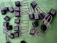
The TO-92 cases look very good like old Toshiba. Outer dimensions measure exactly like my original 2sk170. The dent in the seam on the upper side ist centered, the small circle at the back is flat. I am pretty sure they are original. Main reason why they were still in stock might have been that the article description on sellers Page was wrong. Thats why i hesitated to buy them until only 50 pcs where left..
Thanks for your answer regarding the bias LEDs. I got some matched PF5102 that i will put in my circuit instead of the other fets i use now.
There were those K3xx Toshiba with brown laser etched letters that I have sometimes seen and those with white chalk like letters. Probably older and more common, reminding the print of 2SC2240/2SA970 BJTs. Here's a shot of my few left samples. They came on ammo tape originally.
Attachments
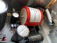
All is boxed and roughly BIASed. Beside the fact that it is absolutely quite during idle, the obvious thing that I noticed first, that it is a way more details presents now compare to what I experienced with Folded. Very pleasant sound for my taste in one hand and highly defined with details sound on another. My both C2+C2Y are 15.07nF (based on my DE-5000). Not sure if I need to go up for C2Y. My MID and LOW bass is pronounced fine. Anyway, I have about twenty of 6.8pF Mallory’s polystyrene caps if needed to add in future. Nevertheless, I need more to burn it and it will require more time for critical listening over different PLs. Based on members request, I’ll try got go to extremes on each dial for C2Ys to see the impact. Final setup and fine tuning is delayed due to damaged C4 cap. Not sure how it happened, but I see cracked-open now. It was not overheated during soldering or damaged during shipment. Just found it cracked-open in the morning. It is totally fine operation-wise, but I can’t leave it in as is. Waiting for its replacement.
Attachments
Very good first impressions Alex. Congratulations for your build. Any pic that also shows the box?
That red shell looks like resin to enclose the foil. I can see a smudge and few hair width scuffs on the white surface near the cracked red end. Maybe it had hit something at the hands of the stockist. Finally a crack expanded with up and down temps.
That red shell looks like resin to enclose the foil. I can see a smudge and few hair width scuffs on the white surface near the cracked red end. Maybe it had hit something at the hands of the stockist. Finally a crack expanded with up and down temps.
Beside the fact that it is absolutely quite during idle
By the way can you remind us the sensitivity of your speakers?
To equal the usual two 50VA double mono ones yes. But electrically even a 50VA double secondary transformer would suffice. When not feeling royal. We mainly suggest no less than 50VA because magnetically shielded off the shelf ones are difficult to find in below 50VA models.
Very good first impressions Alex. Congratulations for your build. Any pic that also shows the box?
That red shell looks like resin to enclose the foil. I can see a smudge and few hair width scuffs on the white surface near the cracked red end. Maybe it had hit something at the hands of the stockist. Finally a crack expanded with up and down temps.
I’ll shoot images with all boxed soon. BTW, it is same boxes from Canada that I used for my second Folded.
Yes, that cap with smudge was suspicious. It’s enclosure is made from some kind of glossy PVC. Never experienced with such behave in the past and I reported that incident to Partsconnexion. They sent me replacement “on the spot” with no questions asked.
By the way can you remind us the sensitivity of your speakers?
It is Acoustic Zen Adagios: 89dB. Tested it with my Audeze LCD-2 headphones and it is also very quite on them too.
Not only about seeing the Canadian boxes but for people to see the wiring also. PSU and phono. Since your build is reported so silent with the volume up.
Yes, will be done soon.
In general, both of my TTs enclosures/bodies are made from dialectic and they are not Earthed. So, my tonearms/cartridges GNDs are floating. This is why I run Phono box Earthed through umbilical cord braid connected to Earth in Raw PSU side box to star GND. BTW, I use Canare L-4E6S quad star cable for umbilical setup.
What is dialectic? That's a classical Greek philosophy term. Maybe dielectric? Using auto correction from a phone? Diabolical software thing. Can twist dielectric material to dialectic materialism. LOL.
") You brought me to my “childhood” time when I been tortured by Materialistic Philosophy and Marxism. The most that I liked is the law of the negation of the negation. I use it daily, till today... If I recall, Philosophy and Scientific Atheism were 4 semesters mandatory course during my Bachelor or Master in USSR.
You brought me to my “childhood” time when I been tortured by Materialistic Philosophy and Marxism. The most that I liked is the law of the negation of the negation. I use it daily, till today... If I recall, Philosophy and Scientific Atheism were 4 semesters mandatory course during my Bachelor or Master in USSR.My iPhone autocorrector is nice feature, but messing things up easily time to time. Conclusion: need to use my glasses!
Last edited:
It is Acoustic Zen Adagios: 89dB. Tested it with my Audeze LCD-2 headphones and it is also very quite on them too.
Not too insensitive, complete system's voltage gain plays a crucial role also, but in general if there was intrusive hiss you would hear it even at 50cm away from their tweeters. Particularly with headphones, no escape.
I know you use 3X gain DCG3 for line duties, but what is the gain of your power amp?
BTW do you still use an active subwoofer to augment those transmission line towers?
My amps (F5T monoblocks) are set to 135W for 6R. So, it is x20 gain (1.42V in/28.4V out prior clipping).
I use my sub time to time to help to my speakers to get a bit down for certain music types. My speakers are tuned for not that deep bass and speakers positions with our room acoustic can’t give me desired effect. So, my sub adds a bit for a missing frequency. I have gigantic sub (B&W ASW-825 -> 1kW) and I set it for 80Hz cutoff on low pass, 2 out of 10 on volume, 0 phase. You probably remember that I had a cupping (rumble effect) issue with my TT, but it resolved by using DYI TT insulation platform.
I use my sub time to time to help to my speakers to get a bit down for certain music types. My speakers are tuned for not that deep bass and speakers positions with our room acoustic can’t give me desired effect. So, my sub adds a bit for a missing frequency. I have gigantic sub (B&W ASW-825 -> 1kW) and I set it for 80Hz cutoff on low pass, 2 out of 10 on volume, 0 phase. You probably remember that I had a cupping (rumble effect) issue with my TT, but it resolved by using DYI TT insulation platform.

I'm updating my existing FSP to UFSP and I have a couple questions regarding some changes
the gain setting resistors R19, R20 have changed values
R19 from 68R to 62R
R20 from 90R to 100R
are these values calculated and need to be changed ?
I see that you also added 5K1 value for R15 I guess gain setting have changed a bit
Also two of the decoupling caps C5, C8 (now part of an RC filter) have changed from 47uf to 100uf. Again is this calculated or tested and thought to be necessary ?
Last edited:
The small changes to R19 R20 are to bring gain values closer to target for resident active parts and the new switch facilities. In the previous there was a 10-12.5mA IDSS Q1 recommendation for HMC & MM modes. Now if higher IDSS Q1 Q2 are used for LMC & MC they will have to stay the same for the other positions. You may still use your older resistors, they will work to little different gains.
100uF caps not absolutely necessary but now there is space to fit them and they contribute to better local RC filtering. You may still use your older 47uF capacitors. They used to be C5 C7 now C5 C9. New C8 is in extra place and its 470uF. In old C8's position there is a C6, again 470uF.
100uF caps not absolutely necessary but now there is space to fit them and they contribute to better local RC filtering. You may still use your older 47uF capacitors. They used to be C5 C7 now C5 C9. New C8 is in extra place and its 470uF. In old C8's position there is a C6, again 470uF.
Thanks for the info Salas,
I'd add to the changes (just to sum it up) the variation of R8 and R11 according to the Idss of Q4 and Q5.
I might have to change those (resistors) too. I have plenty of time till the board arrives.
One more thing: now we lost the F, it's not folded any more, UltraSP
I'd add to the changes (just to sum it up) the variation of R8 and R11 according to the Idss of Q4 and Q5.
I might have to change those (resistors) too. I have plenty of time till the board arrives.
One more thing: now we lost the F, it's not folded any more, UltraSP
- Home
- Source & Line
- Analogue Source
- Simplistic NJFET RIAA