If these came from my kits, this is very suprising. Did you measure the BC560c to see if they came in low as well?
I suspect the measurements are inaccurate for one reason or another. The OnSemi/Fairchild BC5X0c were all high Hfe.
Measurements done properly.
Last edited:
Here's the 50VA Antek in a 2U Galaxy (124 x 230D):
Galaxy 2U w/Aluminum Covers – diyAudio Store
Fits, just. It's a very nice brick of a power supply in hand.
Pharrell, what are you using for an IEC. Do you think it helps? Do you use it as your nominal IEC on all your boxes?
Thanks,
Don
Pharrell, what are you using for an IEC. Do you think it helps? Do you use it as your nominal IEC on all your boxes?
Thanks,
Don
Not the cheapest solution:
5200.1023.1 Schurter | Mouser
But I figure the shielding can't hurt. I have read some stuff about the lower amp versions of these being "quieter" etc. or better at "shielding". No idea about that. I've been using that part in all of my preamp builds—and using headphones to "scope" builds for noise (Thanks 6L6). A build or two have necessitated separating the fuse into its own chamber for jamming into a 1U height, in which case I've been using the non-fuse version of that part, and a separate fuse holder.
I mounted it label down in my Salas PSU for layout purposes only. I would classify my Salas pre as being "pretty damn quiet" for a MI Grado wood body and insane gain thereof with TT preamps and 97db speaks. So far the system is tuned up enough that I can tell right away the quality of a given recording. Have certainly experienced "hum" in my system only to realize it's actually IN THE RECORDING on the record. Haha. Way fun.
Thanks. I've always worried about dragging noise in from the out side. Not that I really know at the box but a lot of urban areas are noisy.
Somebody once posted he thought it changed the sound. I think I worry too much about negative consequences.
Oops, just noticed I mistyped your signature. Sorry.
R,
Don
Somebody once posted he thought it changed the sound. I think I worry too much about negative consequences.
Oops, just noticed I mistyped your signature. Sorry.
R,
Don
Thanks Salas, I was using the 6k2 R3x so tried the 9k1 and it was on the high limits and I could not get tp1/tp2 to settle. Tried a 7k8 and it was on the button. I have both boards tp1/tp2 tracking stable at 3.6v with raw at 35 on one board and 33 on the other. It has been on for a couple of hours and has not changed. I will do an audio test before building up the boxes and doing the proper install. I will then re-check the biasing in the box.
So your Q3x JFETs have strong enough IDSS and simply needed something in between R3x values. Many times people needed about 11k in the later years. Because strong K117GR IDSS picks got gradually depleted. How old was your minikit?
2014 I think, quite early.
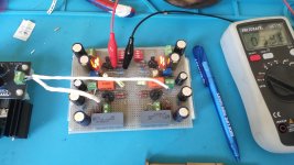
My test board

Making music


My test board
Is it quiet enough in now wide open plan to listen decently for a taste and for its lytics to run in?
What's your cart etc.?
Is it quiet enough in now wide open plan to listen decently for a taste and for its lytics to run in?
What's your cart etc.?
No chance to leave running today sadly but long enough to get a quick flavour. The jump in definition from my previous hotrodded naim cards is enormous as is the size of the image. I can sense there is something very special here and I am very excited. I will build the cases over the next few days and install correctly and re bias. Then I will leave running to burn in during the day and have some serious listening sessions.
Cart is AT-OC5 on a Tabriz arm on a Mk1 Xerxes TT. I have a DIY bootstrap buffer preamp into a highly modified variant of a Naim concept poweramp and then into home made speakers.

Salas helped me to run final electrical test on 1.3S part of new UltFolded to see if 34VDC is stable and has no oscillation or noise. 5mV/dev is used with different time domain. It is absolutely free of oscillation and noise operation. Very clean and stable shunt work. Phono side was connected during test. Please see images bellow.
Attachments
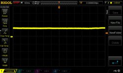
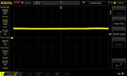
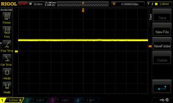
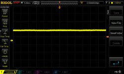
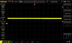
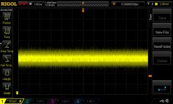
With intensity high up on a DSO no hint of AC patterns in the bars across very slow to very fast time scan. Even on 0.5mV 1uS resolution. Very stable. Don't know what's the measurement loop's own noise, would show residual if shutting down the DUT while keeping the probe where it was, but its nice say 20mS is as thick as 1mS. Usually noise bunches up as we go slow. Due to 1/f noise knee. Your build seems very well executed and unproblematic.
If you also got analog scope handy see 1mS 5mV with same probe same setting same 20MHz bandwidth limit. Should be interesting between real phosphor and LCD screen.
If you also got analog scope handy see 1mS 5mV with same probe same setting same 20MHz bandwidth limit. Should be interesting between real phosphor and LCD screen.
I could not resist to build a matrix board remix of the fsp layout, while i wait for the second run of the ultra fsp GB. I had already sourced and matched a small bunch of 2SK369s thats why i wanted to get started. I wanted to have a kind of test bench to test biasing with the Idss ranges my 2sk170s have. This version is mm only and comes without the gain switches of the new fsp.
Still waiting for my cheap component tester kit i ordered, thats why i had to used unmatched BC327-40 in the cascode.
Testing the LEDs for forward voltage i realized that the orange Kingbright LEDs wont be sufficient to achieve more then 7,5V at 6mA current. I had some random jfets with about 13mA at 12V Vds that made it possible to run my LED quad with about 7,75 V forward Voltage. I had to change R18 from 2.2k to 1k due to the higher Id of the Jfets i used. It works somehow, but i am not sure if this solution is sufficient for the final build?
I used 11mA 2sk369 as suggested. It was easy to achieve 4V at the TP. But powering the fsp proto with a Ultra-Bib 1.3 the bias point was drifting a lot during warm-up of the PSU.
I did not listen to many records yet but i feel that the 2sk369 folded cascode really sounds a bit better then the telescopic cascoded 2sk170s that i used in my last matrix board build. Bass seems to be firmer and stronger without beeing bloomy. Clarity has also improved.
When i play music, the bias voltage starts to fall, when the music stops it rises again. Is this a normal working condition of the fsp construction or a kind of flaw in my implementation?
Attachments
Hi, you don't need reach very high total Vf on the LEDs. There's also the common base transistor adding Vbe. Measure across the K369 for no more than 8V DS. As MM it should have ~2.5mA Id. Readable on its 100R Rs.
Regarding layout and PSU collaboration there can be practical traps, maybe something isn't as perfect as it should be in this proto bed. Given those K369s are testing legit of course. But it could be good enough as a taste.
MM mode should be normally stabler for T.P due to its using a comparatively large value K369 source degeneration resistor. Adjust for after half an hour warm up. Always fully exploit local VR1 before resorting to rail voltage trim when hunting for T.P.
Hi, thank you for answering. Do you mean i can run my LEDs with 6mA @ 7.4 V as long as the voltages are matched between channels?
I observed TP voltage for a longer time and you are right, it doesnt change that much after about half an hour of warm-up. It varies only 3mV while music ist playing.
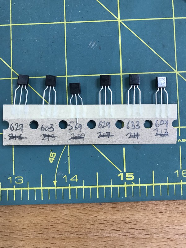
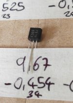
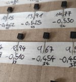
The 2sk369 come from a fishy source (Kessler Electronics) but seem to be the real deal. Rd measures in the 25 Ohm range, Idss vs Vp matches datasheet values. See attached picture of jfets for interest. The bad news is that they are sold out now at Kessler.
I observed TP voltage for a longer time and you are right, it doesnt change that much after about half an hour of warm-up. It varies only 3mV while music ist playing.
The 2sk369 come from a fishy source (Kessler Electronics) but seem to be the real deal. Rd measures in the 25 Ohm range, Idss vs Vp matches datasheet values. See attached picture of jfets for interest. The bad news is that they are sold out now at Kessler.
Attachments
Last edited:
Yes you can run your LEDs at 7.3V or 7.4V without a practical problem in this.
Those last of stock K369s in the photos seem good electrically. RDS is normal for the type. I have cowboy legged white letters samples so I can't compare details about the correct looks of yours.
Those last of stock K369s in the photos seem good electrically. RDS is normal for the type. I have cowboy legged white letters samples so I can't compare details about the correct looks of yours.
- Home
- Source & Line
- Analogue Source
- Simplistic NJFET RIAA