Thanks for the info Salas.
You are welcome
What about if we have the previous version boards and pieces, but haven't started building or acquiring parts for the power supply? Should I upgrade to the 1.3 PSU?
You could skip the PSU components on the previous and connect the output of a UBiB 1.3 PSU at the Rail+ and GND points.
Disclaimer
Before I will be able to hear the Folded Simplistic Ultra in a finished board phono + PSU combination layout I am not in a secure position to make any further subjective remarks than those from my experience with FSP previous powered by regular UBiBs. The UFSP itself has a changed layout and extra switches that may affect it a little or not.
Before I will be able to hear the Folded Simplistic Ultra in a finished board phono + PSU combination layout I am not in a secure position to make any further subjective remarks than those from my experience with FSP previous powered by regular UBiBs. The UFSP itself has a changed layout and extra switches that may affect it a little or not.
A taste of changes
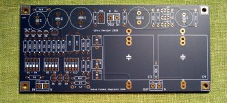
To give you an idea, here is a preliminary channel PCB of the core design I hope to expand into a dual breakable whole including its dual specialized 1.3 PSU sections. In case of difficulties or delays to conclude it as projected due to the weird times we are living through, at least this essential section I have already secured its done and tests well.
To give you an idea, here is a preliminary channel PCB of the core design I hope to expand into a dual breakable whole including its dual specialized 1.3 PSU sections. In case of difficulties or delays to conclude it as projected due to the weird times we are living through, at least this essential section I have already secured its done and tests well.
Attachments
follow on regarding UFSP
I will follow on with some pictures of the boards built up and in action - as well as some preliminary differences.
We started at beginning of year with these boards and standard UBIB power supply.
The sonic results were solid, the main constraint being cap break in and setting the inbound voltage to the signal board. It drifted enough to make the test point settings time consuming.
sonically, listening to this on aljorden system ( I will ask him to write some words too), we can tell the pre does image/instrument separation a bit better than the original design does, and tone again seems a bit richer once you dial in the power supply and the C2Y cap. Sonically, it sounds a bit more organic than the previous version with similar caps, less electronic signature. But this is only my opinion. I usually don't want to make any promises for a board I might sell, but I have spent a lot of time listening to this project. I am certain the C3-C4 caps and resistors you put in the circuit play a role in the sonic outcome.
We listened overall 3-4 different cartridges. Their strength and weakness all became apparent.
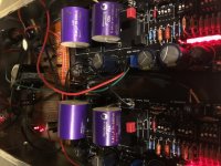
The power supply at 36 Volts and varying current made setting the test point a day long process to be consistent, less so with MM settings. So Salas designed a modified UBIB to keep the voltage from drifting. Here with the purple caps you can see my rough veroboard implementation of it with fets on the chassis floor for proof of concept. The voltage now is solid on the PS side and takes some time for warm up to set the Test point on the signal board side.
I am very happy with the improvements made, we can now change the settings for gain with no resistor swaps, and therefore play with ideal gain settings for your cart. Also spent a lot of time testing 2SK369BL Jfets to be able to run pairs in a really wide range of them too.
I think overall, it will still take some setup time, still an expensive project - but it becomes a more flexible and simpler project to complete and dial in.
I will follow on with some pictures of the boards built up and in action - as well as some preliminary differences.
We started at beginning of year with these boards and standard UBIB power supply.
The sonic results were solid, the main constraint being cap break in and setting the inbound voltage to the signal board. It drifted enough to make the test point settings time consuming.
sonically, listening to this on aljorden system ( I will ask him to write some words too), we can tell the pre does image/instrument separation a bit better than the original design does, and tone again seems a bit richer once you dial in the power supply and the C2Y cap. Sonically, it sounds a bit more organic than the previous version with similar caps, less electronic signature. But this is only my opinion. I usually don't want to make any promises for a board I might sell, but I have spent a lot of time listening to this project. I am certain the C3-C4 caps and resistors you put in the circuit play a role in the sonic outcome.
We listened overall 3-4 different cartridges. Their strength and weakness all became apparent.
The power supply at 36 Volts and varying current made setting the test point a day long process to be consistent, less so with MM settings. So Salas designed a modified UBIB to keep the voltage from drifting. Here with the purple caps you can see my rough veroboard implementation of it with fets on the chassis floor for proof of concept. The voltage now is solid on the PS side and takes some time for warm up to set the Test point on the signal board side.
I am very happy with the improvements made, we can now change the settings for gain with no resistor swaps, and therefore play with ideal gain settings for your cart. Also spent a lot of time testing 2SK369BL Jfets to be able to run pairs in a really wide range of them too.
I think overall, it will still take some setup time, still an expensive project - but it becomes a more flexible and simpler project to complete and dial in.
Attachments
As a matter of fact I had designed the special Ubib version for the phono months earlier. But I kept it in the drawer not to enlarge the project if not practically proven to be called for. If regular Ubib had best suited it the whole thing would be ready to go now. But no such luck.
")
I agree, on of the shortcomings of FSP was the difficulty to change gain setting. Not difficult to implement (very few components to change) but not for on-the-fly change (I think quite a few people have more than one cartridge)
Also, what I concluded is that UBIB has more energy than BIB (which has more weight and is more relaxed). Because dynamics is one of the very few elements of FSP thah I wish it could be improved, I welcome this change. It's a tough game to try to please everybody and hold it's ground against much more expensive commercial phono stages.
Could I suggest that the space of the output cap could be little bit bigger.
Could I suggest that the space of the output cap could be little bit bigger.
The coupling film caps space was debated, because widely diverse, finally adopting the modern form factor of Mundorf EVO and ClarityCap CSA/CMR lines, for their popularity and broad price range span.
It's a tough game to try to please everybody and hold it's ground against much more expensive commercial phono stages.
I was persuaded to revisit it based on builders requests, it has held in time quite well indeed. Entering a new decade now.
I've been listening to the new boards for a little over two months now. I am using the standard UBIB boards for the power supply, not the new regulated boards. I've tried all the different gain levels with different cartridges - MM, high output MC, and a couple of low output moving coil cartridges.
I used two chassis so I could separate the power supply from the RIAA boards. When I change gain, I initially adjust the voltages on the power supply and the RIAA boards, then check about 4 hours later and readjust, then check the next day and readjust if needed. I've settled on 55 dB of gain for the two cartridges I use, and the voltage stability has been rock solid since I've last changed the gain 5 weeks ago (I never turn the unit off).
As to sound, unfortunately I don't have any experience with the earlier version of the RIAA boards, so I can't offer any comparison. When Tea-Bag hinted of its sound signature, I thought it probably wouldn't fit my tastes (I like warm and full, and he said this would be very detailed sounding). However, I think it sounds amazing. I find it uncolored, very full sounding on full sounding recordings, alive and detailed, and excellent throughout the frequency range. There is not a hint of stridency. It is silent regarding hum and noise, even at its highest gain setting, into my most efficient speakers (99 dB).
I have an analog-only buddy who listened to it for a long while. He uses the Pass XP-25 as his phono stage. He is very forthcoming when he hears problems in audio gear. He loved it.
I will follow on with some pictures of the boards built up and in action - as well as some preliminary differences.
We started at beginning of year with these boards and standard UBIB power supply.
The sonic results were solid, the main constraint being cap break in and setting the inbound voltage to the signal board. It drifted enough to make the test point settings time consuming.
sonically, listening to this on aljorden system ( I will ask him to write some words too), we can tell the pre does image/instrument separation a bit better than the original design does, and tone again seems a bit richer once you dial in the power supply and the C2Y cap. Sonically, it sounds a bit more organic than the previous version with similar caps, less electronic signature. But this is only my opinion. I usually don't want to make any promises for a board I might sell, but I have spent a lot of time listening to this project. I am certain the C3-C4 caps and resistors you put in the circuit play a role in the sonic outcome.
We listened overall 3-4 different cartridges. Their strength and weakness all became apparent.
The power supply at 36 Volts and varying current made setting the test point a day long process to be consistent, less so with MM settings. So Salas designed a modified UBIB to keep the voltage from drifting. Here with the purple caps you can see my rough veroboard implementation of it with fets on the chassis floor for proof of concept. The voltage now is solid on the PS side and takes some time for warm up to set the Test point on the signal board side.
I am very happy with the improvements made, we can now change the settings for gain with no resistor swaps, and therefore play with ideal gain settings for your cart. Also spent a lot of time testing 2SK369BL Jfets to be able to run pairs in a really wide range of them too.
I think overall, it will still take some setup time, still an expensive project - but it becomes a more flexible and simpler project to complete and dial in.
Last edited:
I was persuaded to revisit it based on builders requests, it has held in time quite well indeed. Entering a new decade now.
I was one of those, I was gonna try revise it myself but my projects list was quite big, I mean I finished my DCB1 yesterday (late comer or what ?). Instead I've upgraded the gain output caps to copper ones from Miflex.
Another suggestion is to have little space around 2sk369s (1-2mm would do) and two tiny holes close for small cage (copper ?) for them.
I guessing that caps pitch are about 40mm, good for gain cap but not for output. Although Mundorf, Clarity and Rike have opted for bigger width caps, the majority of them are full length, especially the copper ones. For those caps 70mm pitch is preferable. Even-more, I think that most people would prefer old Supreme series than the new EVO series for signal.
Even-more, I think that most people would prefer old Supreme series than the new EVO series for signal.
EVO are not only the cheaper than Supreme versions. 2.2uF C4 EVO starts with a 4 Euro plain dry one and tops with an oiled and gilded ~100 Euro boutique type. Both price extremes and those in between fit the boards so there is expanded choice.
ClarityCap CSA & CMR fit as well. Those are cheaper class and upper middle class excellent British caps of solid engineering. Problem with longer traditional film caps is they are all over the place for dimensions. Can't predict for more than a couple of types on a well proportioned PCB layout. When the fatter/shorter types look like more compatible between makes and ranges.
By the way, Supreme 0.1u and other alike form factor types still fit for length in the new C3's space. Inter-stage is arguably the more influential coupling position in this phono.
Also when you look again there's an embedded trick. Both C3 & C4 places are non blocked at one side and secondary extra wide inlet pads are included. So very long loudspeaker crossover style film caps (even if with wire ends) can be allowed to overextend the board's edge. It will look odd with one third hanging but they can be employed if already owned or opted for.
We added some large holes here for some larger loudspeaker caps. I forget the dimensions.Also when you look again there's an embedded trick. Both C3 & C4 places are non blocked at one side and secondary extra wide inlet pads are included. So very long loudspeaker crossover style film caps (even if with wire ends) can be allowed to overextend the board's edge. It will look odd with one third hanging but they can be employed if already owned or opted for.
YesWill the new version still work with the existing raw power supply?
Resisors differences?
Hi friends
I must admit I lust for the Simplistic NJFET RIAA, even though I have several other projects unfinished.
Right now, I'm at the stage of trying to establish a cost-estimate per the BOM...
2 boring questions arose:
- Being a beginner (DCB1 is the most complex build I have achieved), and this thread being, well, impressive in both length and expertise, what would be the experts advice: try, or die (too complex a project for me?)
- Not having done resistor-rollings, how would you characterize the various brands (CMF55 / PRP / Takman) impact, sound wise?
Thank you all so much
david
A few photos of my second build of this magic design. Had quite a time of this build and needed to look very carefully at Salas's advice to other builders to get to grips with difficulties in getting the voltages in the ballpark to set the bias to 3.60V in each channel. Couldn't have done it without you Salas. Your sage advice to elwood set me on the right path.
I think one cause for me was an external one: our notional mains supply of 230V spends most of its time very close to 250V so the raw supply was over 53V in each channel. After addressing that problem with the addition of 18R 5W in place of the links in the raw supply, I then needed to adjust R3x in each channel to bring the voltages within the range of the trimmers, ending with about 34V in each channel to give the required 3.60V between TP1 and TP2.
Had another interesting experience with C3. Initially fitted a couple of very large Russian .1uF caps but they had the unfortunate ability to act as antennas for every 50Hz signal within cooee. Fortunately I had in my collection a couple of Wima FKP1 .047uF and they solved the problem perfectly.
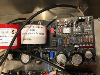
You will note that I have built the power supply in the same enclosure, ensuring that it is shielded from the main boards by a steel plate effectively having the PS in a Faraday cage as the enclosure is also steel. Of course the proof is always one's ears and the preamp is free from hum.
My first FSP build has gone to a good home as the phono preamp for a Rega Planar t/t, a better than average Marantz amp and some 90s vintage Mirage speakers. The owner is a the music theatre tragic so the system has a new lease of life with South Pacific, West Side Story, Cabaret etc filling the house. She is ecstatic with the sound quality.
My new build takes its signal from my Garrard 301 with AT150 cart and feeds to Linear Audio 5 Doug Self preamp and then to my Silicon Chip Class A amp and Magnepan speakers.
I think one cause for me was an external one: our notional mains supply of 230V spends most of its time very close to 250V so the raw supply was over 53V in each channel. After addressing that problem with the addition of 18R 5W in place of the links in the raw supply, I then needed to adjust R3x in each channel to bring the voltages within the range of the trimmers, ending with about 34V in each channel to give the required 3.60V between TP1 and TP2.
Had another interesting experience with C3. Initially fitted a couple of very large Russian .1uF caps but they had the unfortunate ability to act as antennas for every 50Hz signal within cooee. Fortunately I had in my collection a couple of Wima FKP1 .047uF and they solved the problem perfectly.
You will note that I have built the power supply in the same enclosure, ensuring that it is shielded from the main boards by a steel plate effectively having the PS in a Faraday cage as the enclosure is also steel. Of course the proof is always one's ears and the preamp is free from hum.
My first FSP build has gone to a good home as the phono preamp for a Rega Planar t/t, a better than average Marantz amp and some 90s vintage Mirage speakers. The owner is a the music theatre tragic so the system has a new lease of life with South Pacific, West Side Story, Cabaret etc filling the house. She is ecstatic with the sound quality.
My new build takes its signal from my Garrard 301 with AT150 cart and feeds to Linear Audio 5 Doug Self preamp and then to my Silicon Chip Class A amp and Magnepan speakers.
- Home
- Source & Line
- Analogue Source
- Simplistic NJFET RIAA