Thanks
Thank you, I’m very happy with this project.
Ok then I’ll get things setup for the fft tests on hum. Be great to see the visual representation on screen. Loving the scope btw. This will be a great experiment/ experience for using fft function. I’m out today but will setup tomorrow.")
Thank you, I’m very happy with this project.
Ok then I’ll get things setup for the fft tests on hum. Be great to see the visual representation on screen. Loving the scope btw. This will be a great experiment/ experience for using fft function. I’m out today but will setup tomorrow.
2SK117GR
Hi
I am about to start the build and have been measuring the 2SK117GR's to find out which ones to pick for Q2x, Q3x, Q5x and Q7.
All of them are from one of Tea-Bag's minikits from 2014, which I have just bought from another diyaudio member who abandoned the project.
The IDSS is measured as described in Transistor matching using a 9V lab supply and my Fluke 87V.
In the build notes it is recommended to use 2SK117's with IDSS in the 3-4mA range for Q2x, Q3x, Q5x and 4-5mA range for Q7. As shown below most of mine measures higher than that:
1: 3.73
2: 4.89
3: 4.98
4: 5.18
5: 5.22
6: 5.28
7: 5.29
8: 5.35
9: 5.66
10: 6.14
My question is if its ok to use them and which ones to pick for Q2x, Q3x, Q5x and Q7?
Thanks
Hello
Q7 6,7
Q3x 4,5
Q4x 2,3
Q2x 8,9
The guide's BOM has an asterisk also that says "*If batches of 2SK117GR are yielding circa 5mA IDSS then use 6.2K R3x 0.5W and 33R R6x"
Just saw that you put Q4x in your answer. I guess you meant Q5x for 2,3?
Hello
Q7 6,7
Q3x 4,5
Q4x 2,3
Q2x 8,9
The guide's BOM has an asterisk also that says "*If batches of 2SK117GR are yielding circa 5mA IDSS then use 6.2K R3x 0.5W and 33R R6x"
Just saw that you put Q4x in your answer. I guess you meant Q5x for 2,3?
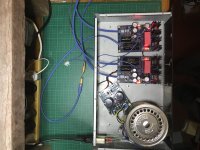
How not to enclose your FSP
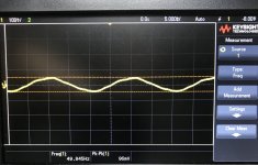
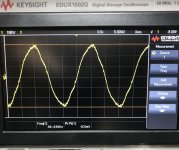
As you can see in the photos, there is a small hum around oh let’s say 50Hz , maybe coming from the transformer .
See the 96mV being picked up before I connected the output, then straight up over 600mV when connected.
As you can see in the photos, there is a small hum
around oh let’s say 50Hz , maybe coming from the transformer .See the 96mV being picked up before I connected the output, then straight up over 600mV when connected.
Attachments
Hi Bix,
Your AC path is short, direct. Good planning.
Try to rotate the transformer and see if it changes. Nice 'scope.
Don't forget that the output is also another input, so you might have to dress your speaker leads away from the mains plug and outlet in case they run close.
-Chris
Your AC path is short, direct. Good planning.
Try to rotate the transformer and see if it changes. Nice 'scope.
Don't forget that the output is also another input, so you might have to dress your speaker leads away from the mains plug and outlet in case they run close.
-Chris
He should also attach the thinner pcb zero blue cables on the chassis before making them to Y for meeting the TT's ground lead. The raw dc board's earth isn't going to the chassis also it seems. There are further possible test things after doing those things mentioned. Like lifting a leg from one of those 1R if there is a loop because single chassis, safe lifting the mains earth from the chassis with a bridge and RF bypass etc.
Hi Salas,
No, the AC mains ground must connect directly to the chassis. The signal ground should connect to the chassis through a resistor to break any possible loop. That way the user is protected as he should be, and the signal ground does not suffer a loop. Usually a resistor between 10 and 100 ohms is used.
-Chris
There's a phono box at pcb's regulated psu ground potential to shield best and attach the TT's ground wire lug. The zero lines also go back to another box that houses trafos and the raw psus through loop breaking resistors and yin yang diodes to the mains protective earth. That box is at PE directly. Between them boxes the umbilical's screen is only one way connected.
By the way 600mV pk-pk is 212mV RMS and Bix would have had a big loud hum at the speakers and not some "bit of hum" as he describes. The probe's very high impedance must be allowing more than his amp's input load or there is more mains earth looping between the scope and his handy test chassis. Especially if the probe is not on spring tip short gnd and near enough to that big trafo.
Sounding good though. Bit of hum as expected.
- Home
- Source & Line
- Analogue Source
- Simplistic NJFET RIAA