Hi Nick, when i tested my FSP with generator and L pad to see the frequency responce I did use Sinusoidal waveform of course. For a moment I use Square and sawtooth for fun, and I realize that those are "converted" to Sinusoidal to the output, specialy square. Is that ok or because of charging of the serial capacitors or i have to worry about?
You would need anti-Riaa filter to pass other than sinusoidal in resemblance to its true form. Because the Riaa EQs them out of shape.
The 2nd board came right up as well, TP1-TP2 was 3.65 or so on that one without adjusting anything. TP-1 to ground was 7.76V on the 1st board, and 7.73 on the 2nd, which should be the voltage across the 4 LED string, so about the same as what I measured when I matched these. I did heed your advice and use the 2SK117 (Q7) and a 3.3K resistor with a bench PSU and did the whole string instead of measuring individual LEDs.
I wanted to ask; I used Nichicon KZ caps as I had been told that the newer Elna Silmic IIs aren't as good (Wayne from Pass Labs said he had quit using them). I see from pictures that a lot of people seem to use them.
I also bought some Panasonic FRs, but the lead spacing is smaller than the foo foo caps are, so not sure how well they would fit.Big plus in the 105*C rating and 10,000 hour life vs. the 85*C / 1000 hours of the KZs and probably similar in the Elnas. The brown wrapper on the Elnas is IMHO fugly as well, but didn't consciously enter into my decision.
The hours rating doubles with each 10*C below their nominal ambient temperature spec so the 1000 hour 85*C capacitors are good for 24000 hours at 40*C temperature in the box. My original build in the manual has Nichicon Muse KZ. I also like their Muse ES bipolar.
Interesting behavior... I put 150K/200K in for R2x/R3x (with 100K for R1x, 47K for R1). When measuring input loading with a bench meter (HP3468), on one board, it will be reading as expected when switching various loads in, but suddenly jump to 6.7K or so and stay there, no matter what switch combination is selected. Putting a Fluke hand-held meter on it immediately reads as it should. Is the bench meter turning Q1 on? Bizarre.
Hi Nick
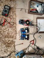
Phono MC low assembled in final chassis (photos to follow later), and i was taken some measurements to adjust it
I make the following list in a 3hours:30 mins period , measuring the TP1-TP2 Voltage and here are the results . Temperature in the room is around 25-26 Celcious
Time TP1-TP2 V % offset from 3.6V
0:00 0.573 -528.27%
0:15 1.503 -139.52%
0:30 2.170 -65.90%
0:45 2.631 -36.83%
1:00 2.942 -22.37%
1:15 3.184 -13.07%
1:30 3.401 -5.85%
1:45 3.565 -0.98%
2:00 3.663 1.72%
2:15 3.769 4.48%
2:30 3.883 7.29%
2:45 3.950 8.86%
3:00 3.969 9.30%
3:15 3.968 9.27%
3:30 3.987 9.71%
3:45 4.010 10.22%
Seems that TP1-TP2 Voltage needs about 2 hours to reach the 3.6volts but it keeps raising, do you think is ok or i need to adjust the trimmers for less Voltage so it wont go at the 4volt range?
Thanks in advance
Last edited:
Check from C3's input point to ground for when its 4V and for what TP1-TP2 Voltage that happens. So you will know the exact TP1-TP2 target regarding your parts tolerances. Then keep that as median reference to float about with your trimmers.
If I understand you actually mean Voltage accross C2
V C2 TP1-TP2
4.115 3.623
20 mins later was
V C2 TP1-TP2
3.986 3.743
So what you mean by target reference to try to keep
Yes saying across C2 its the same thing. So keep as your TP1-TP2 median the 3.74V figure.
Just start from cold with the case closed, have test leads on the test points that connect to a DMM outside, in an hour quickly trim for that median. Then close the case and leave it alone.
Just start from cold with the case closed, have test leads on the test points that connect to a DMM outside, in an hour quickly trim for that median. Then close the case and leave it alone.
Yes saying across C2 its the same thing. So keep as your TP1-TP2 median the 3.74V figure.
Just start from cold with the case closed, have test leads on the test points that connect to a DMM outside, in an hour quickly trim for that median. Then close the case and leave it alone.
Thanks Nick
I do work on a closed case with test leads come outside the box for measurments anyway. If I open the lid even for few seconds voltages go away
So I need that median value within an hour, that's what I needed to Know.
Do I need to check those Voltages when room temperatures raise during summertime? ( Or use the aircondition
)
Last edited:
Hi, I have quite high V+ differences between my two boards. I have a raw dc supply of 50V for both but in one channel I have 3,6V TP1-TP2 with V+ 32,5V in the other I had to use 8,2K as R3X to achieve the 3,6V but with V+ of 37,25V. If I reduce R3X to 5,6K TP1-TP2 is 7,6V and no way to reduce it. Isn't too much difference is it?
Yes it is but there can be tolerances to impose such a DC difference. Try with VR1 also. The key is to have almost the same signal gain between your two channels. Do you have any means to check that? Like a test record, function generator, oscilloscope, DMM on AC, sound card and FFT software, whatever. (You have to make make 1:100 voltage divider with 1k&10R resistors in a connector and shielded cable for driving clean low mV from lab gen or pc card)
Quick question which I probably already know the answers to. I haven’t gotten my turntable out of storage yet, but after mounting the phono stage and all on a piece of particle board, I hooked up a headphone amp and did a bit of testing.
1) Significant amount of hum at mid volume and above. The inputs were open; I would guess I might want to short them for anything meaningful?
2) I have the inputs wired as twisted pairs (mm configuration). Touching either of these, or getting my hand near one increased the hum. I think I will redo with coax?
Will get the turntable out in the near future...
Dear Salas,
I am going to try the new CLEARAUDIO Charisma MM cartridge which will require that I re-configure the phono amp.
From looking at the schematic with my dilettante's eyes I wonder: is it really necessary to remove one of the 2SK369? I am assuming that it is not as necessary for noise reduction for MM as it is with MC but since it looks like it is simply in parallel ...
Would this require different values for R13 if retaining the pair. I know if I keep the pair I will need to use both R2 & R3.
Needing 40 dB of gain could you suggest to me what I should use for R2/R3/R13 if this is advisable. I will likely return to MC mode and would rather not take the chance of cooking that hard to get FET.
Thanks and take care,
Quick question which I probably already know the answers to. I haven’t gotten my turntable out of storage yet, but after mounting the phono stage and all on a piece of particle board, I hooked up a headphone amp and did a bit of testing.
1) Significant amount of hum at mid volume and above. The inputs were open; I would guess I might want to short them for anything meaningful?
2) I have the inputs wired as twisted pairs (mm configuration). Touching either of these, or getting my hand near one increased the hum. I think I will redo with coax?
Will get the turntable out in the near future...
If you are using the RAW DC board lift one of those 1R and see if that makes a difference at least for when the build isn't housed in a grounded box yet
^ I'm not (I'm using a pair of GRLV supplies). No connection to ground or AC ground pin currently.
I know on discrete headphone amps I have built, the inputs need to be shorted if testing without the pot in. I know that R1 || R1x-R4x do provide input loading. Shorting the inputs may only mask issues?
Is testing in this manner even valid? Just trying to do as much performance validation as I can before I get the table out.
Yours is not a standard build for board and PSU so I can't tell for sure if there are issues right now. Normally its reported quiet even in MC mode without any special measures while just thrown around. Tell me your DC voltage on the drain of each JFET vs GND and if there's no doubt they are originals.
"Playing fine, noise is close to zero without a box."
"Playing fine, noise is close to zero without a box."
Attachments
- Home
- Source & Line
- Analogue Source
- Simplistic NJFET RIAA