2 x 22 in parallel = 11r. 11 works a treat thanks legend. I only had crappy resistors I bought in variety pack of the net but there working okay. Definitely gonna replace with something better soon. But hey presto! Things are looking good. Can’t believe after four very disruptive years I’ve finally got it working. What a bloody marathon build. Now it needs a case... another four years.
Unfortunately I can’t plug it in and have a listen because I’m away from home for another week, sheez just have to wait.
Unfortunately I can’t plug it in and have a listen because I’m away from home for another week, sheez just have to wait.
Weird that it was alright and then stopped on its own. Maybe some probing incident (?)
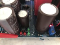
Check if the LEDS are good first. Small diameter ones are weak for heat and can be compromised during soldering to fail later. If one breaks the whole chain goes down. Use the DMM's diode check mode and see if each one lights up on its own. That Tenma (UNI-T) has enough voltage to light up LEDS. Red probe to anode black probe to cathode. They can be tested in that way as they remain installed on the board.
About Q7 I would be less suspicious initially as it does not have to dissipate much and that position does not have a bad reliability record. Anyway to check its good it should show neither a short nor high resistance between its outer pins. Something like 50-100 Ω for this type. It can be tested in that way without removing it from the board.
Those tests should be performed only while the FSP is powered down.
Yes its early hours here. That steady R15 voltage means there is constant current drawn by Q7 but it does not charge up C8 as it finds another path. I am increasingly suspicious of Q3. First redo its soldering. Then check if at any point during the weirdness it develops some Vbe or not. ~0.6V steady Vbe would be its normal state. Also check the drop across R13. Not one of its pins VS ground, across its pins.
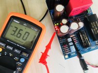
Who would have thunk it aye? Bad cap, maybe I did short it somehow. Anyways I’ve only got a 220uf on hand but it lights up. I’ll order in replacement ASAP. Rail + 35.56 TP1 - 2 is around 3.5 - 3.6. ")
Attachments
Last edited:
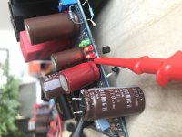
I’ve binned the old cap, it was definitely faulty, slight bulge and I could feel it heating up under the PCB. A great learning experience though, fun working through the schematic with you, thanks so much. Learning loads btw.
Looking forward to hearing it and setting gain and load. I’ve gotta dl103r, not to sure how load is calculated?
I’ll buy a lottery ticket tomorrow
Looking forward to hearing it and setting gain and load. I’ve gotta dl103r, not to sure how load is calculated?
I’ll buy a lottery ticket tomorrow
Last edited:
I have a Denon 103R too. Now its in its box as I use an AT33PTGII. At circa 200R load it sounds well balanced IMO. Both do in fact. Its either one known value resistor selected on the DIP switch or parallel combinations as you switch on more positions. The DMM measuring Ohm (not Ohms as its established, Ohm was a man) across the signal input will tell. No need to calculate.

- Home
- Source & Line
- Analogue Source
- Simplistic NJFET RIAA