I think there is no difference, at DC at least. You are right on the Ib current. Do you think to replace the fet with a stronger one? Is any reason ?
No reason. The VF you got is enough.
Still plugging away at it
Hi Salas, so I’m short on a few parts, but have made some progress. Q3y hfe both around 608. Is this orientation correct?
All a little dusty like my brain. 😜
Thanks Salas, you were very helpful when I started. I’ll dig everything out and blow off the dust from my brain. I suppose I was hopeful somebody local to me might have time and the skills required to finish it off. It’s been a while.
Hi Salas, so I’m short on a few parts, but have made some progress. Q3y hfe both around 608. Is this orientation correct?
All a little dusty like my brain. 😜
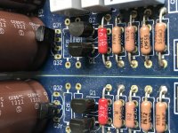
Correct orientation and transistor type for Q3y position
If only my build time was as fast as your response time.
P.S. Notice that if your own LED strings don't exactly reach the total forward drop voltages quoted in the instructions its not a problem, you just want them strings total voltages fairly well matched between the channels. Since the rest are already done and installed in in your case except D1x just match two reds for D1x to complete the PSU circuits.
Hi Nick
I put the Phono in a carton box with adequate ventilation just to simulate the aluminum box will be in the near future so to adjust the TP1-TP1 bias
I see that even in the box the bias is raised slowly but in a continuous way up to maybe over 4Volts, and some time i do have to re-adjust VR2x to the limit and still can't go lower enough to 3.6V, I also use VR1 to lower the voltage but still raise slowly but continuous.
From cold start I see that it may takes an hour or more to reach 3.5-3.6V (without re- adjustement from previous session it starts cold from 1V or less and gradually raise to 2-3V in a hour or so).
I wonder if I put a plastic cover over the two K369s to isolate them (in a way) from the enviroment which is getting warm from the Power Supply Heat
Any ideas?
Last edited:
Ok will match 2 leds pronto.
Next question, R2 and R3. I have a dl103r, so will need to set for 60db gain? I don’t have any IDSS info listed, foolishly misplaced. I would guess around 11 mA. Working from the PDF, 3.9 ohms would be correct?
Yes and yes
You could try a cover or to swamp them with a hot melt gun. Anyways you only look to keep an equidistant point they would hover about because MC version input stage may drift but still keeps enough DC voltage window to contain the few decades of mV level signal swing.
So as a middle point considered the 3.6V plus minus ~0.5V?
There can be some adjustment of resistor values to recommend for your intermediate target gain. But first I need to know your cartridge model and the IDSS of the K369 you have installed.
My cartridge is a Lyra Argo. The IDSS of the K369's is 10.
Thanks for your help.
My cartridge is a Lyra Argo. The IDSS of the K369's is 10.
Thanks for your help.
Will let you know soon.
So as a middle point considered the 3.6V plus minus ~0.5V?
Its fine. Even more +/- TP1-TP2 DCV allowance between cold start and well warmed up would not be disastrous.
Circuit Description
Hi Salas, Is there a circuit description for the FSP like the DCG3 thread post #47?
I’ve been trying to better understand how this circuit works. I’m loving this project and very happy I’m finally getting back into the hobby.
Many thanks as always, for all your knowledge and support
Ps: I’m slowly getting through the 1600 + pages of this thread.
Last edited:
- Home
- Source & Line
- Analogue Source
- Simplistic NJFET RIAA