Thus a reading of Vres=6.80Vdc means the current is 6.8mA (LED very bright) and a reading of Vf should be 2.2Vf (probably a green, or yellow)
Why am I interested in the current? I am not interested if the led will light up or not ; i am only interested that the led series will drop a total 7.54 V to have a ground reference as requested in the guide to assemble the quad; Or am i missing the point?
I chose this way to be able to measure very strict the drop with the tool i have.
I use a 9V battery with the measured voltage of Vbatt=8.878V
1.5K resistor 0.1% (which is nothing compared to the Voltmetters MegOhm resistance)
Voltmeter with auto range that gives me the voltage after the diode Vrest.
I obtain the Vf or the voltage drop on the led/diode Vf=Vbatt-Vrest and it clearly differs from the Vf reported by the DMultimeter on the diode setting.
Am i making a mistake ?
Thank you!
Edit: I took as measure the addition of an extra led in series for each (quad for RIAA and trio for supply) in order to reach the stated reference voltages. My hope is that such a big difference (of about 1.3V) results in a mistake in my measuring but i do not see how this is the case at this point.
Thanks again ant i eagerly await experienced guidance
")
Last edited:
Bloody hell !
the Vf of a LED varies as the current varies.
Plot a Vf vs Iled and see for your self.
Do you know what current will flow through the Vref string?
If not, then you need to find out what that is and what range of adjustment is available to trim the Vref final operating voltage.
YOU NEED CURRENT.
the Vf of a LED varies as the current varies.
Plot a Vf vs Iled and see for your self.
Do you know what current will flow through the Vref string?
If not, then you need to find out what that is and what range of adjustment is available to trim the Vref final operating voltage.
YOU NEED CURRENT.
Bloody hell !
....
YOU NEED CURRENT.
Thanks; I understand where is my mistake now
. hard... but ...Whew.BTW, this thing sounds FANTASTIC
Compared to Pearl II?

Broadly similar in sound, which is to be expected due to the active devices and topology being from the same school. (Toshiba and RIAA all in the middle)
They are both very, very good, quiet, tuneful, accurate, and musical. The biggest difference in my experience is the Pearl is a better project for the less-experienced builder, as the Salas has more configuration options and you need to build it one way.
(As an aside, my assumptions says the "best" or "most ideal" configuration for the Salas is as I built it, ~40db gain made ideal for MM, and if you want MC, use a step-up transformer. )
Is one better than the other for sound? Doubtful. They are both WONDERFUL! Smart designers make amazing designs. Nick and Wayne both know what they are doing.
Compared to Pearl II?
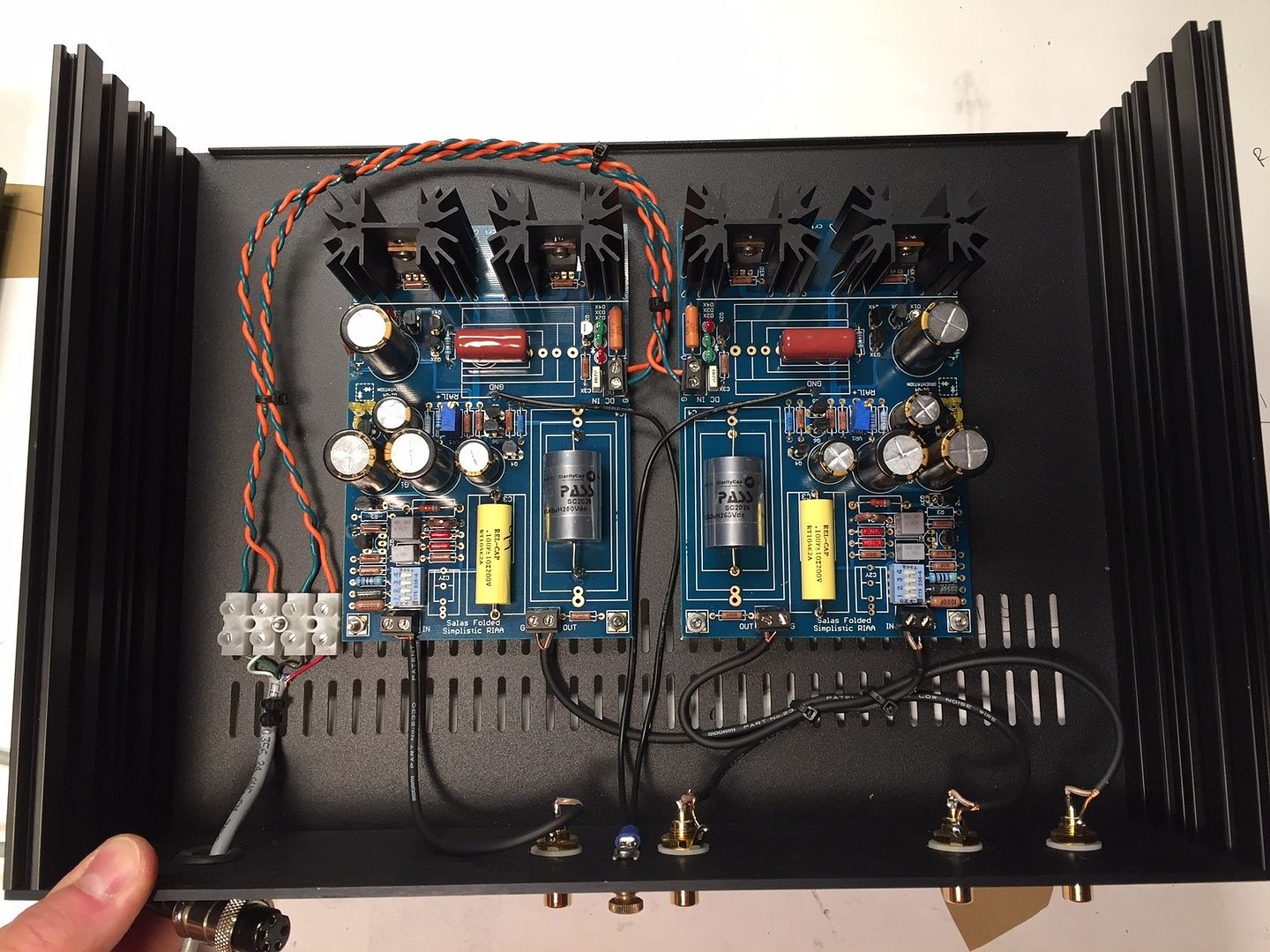
Nice pictures, looks well put together. The FSP is also very adept for direct MC use without an SUT due to the low noise doubled up JFET type in high gain folded cascode configuration. There are some affordable MC carts like the Denon DL-301MKII or moderate models from the audio-technica and Ortofon line-ups that can take advantage.
No question that the FSP can be made to suit whatever cartridge! That's the genius in your design.
I was saying that, in my opinion, the broadest flexibility would be for 40-50db gain and the use of a SUT with MC. But that's just one way of doing it. The user has an Ortofon 2M bronze currently.
I was saying that, in my opinion, the broadest flexibility would be for 40-50db gain and the use of a SUT with MC. But that's just one way of doing it. The user has an Ortofon 2M bronze currently.
The 2M bronze is a quick clean and dynamic cart that maybe leans a bit to highlighting brilliance. But it depends on how it complements the rest of the system's tonal balance. Especially the speakers-room result. A smooth contender in its price range worth mentioning would be the Nagaoka MP-200 offering a jump to the boron cantilever category where's less mechanical resonance in the audio spectrum.
If a good SUT is already owned it offers flexibility to build for MM and combine it when rotating MM and MC carts. Especially when having a removable headshell and easy height adjustment tonearm. If not, I would prefer to better spend the SUT money difference in best MC cart I can get hold of and build for straight MC option. The AT ART9 is a superb alternative when thinking vs a medium priced MC + good SUT combination expenditure for instance.
If a good SUT is already owned it offers flexibility to build for MM and combine it when rotating MM and MC carts. Especially when having a removable headshell and easy height adjustment tonearm. If not, I would prefer to better spend the SUT money difference in best MC cart I can get hold of and build for straight MC option. The AT ART9 is a superb alternative when thinking vs a medium priced MC + good SUT combination expenditure for instance.
Thanks; I understand where is my mistake now
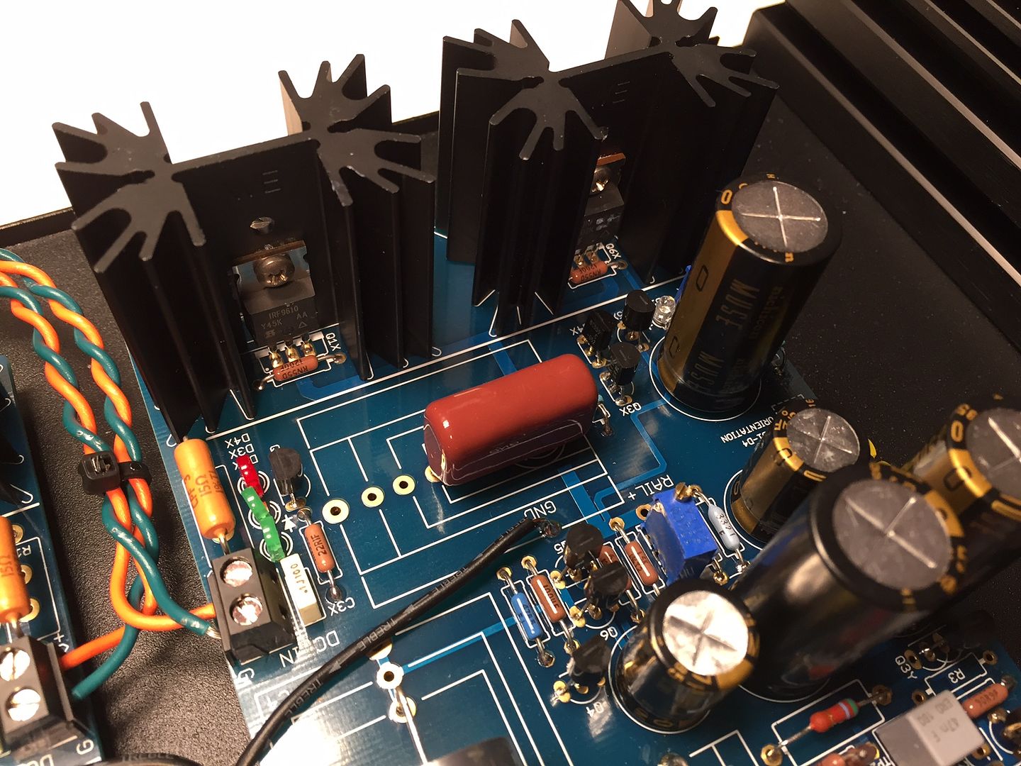
The in-circuit four LEDs current will be that of Q7's IDSS. So test Vf with that current in mind. Do an online search on how to test NJFETs for IDSS if not noted already for your Q7s. In my prototype I must have used rather higher than average Vf Leds so don't be too concerned in meeting their total Vf exactly. LEDs of say 1.8V Vf at 5mA which are fairly common can also do, just go for 3.3V TP1-TP2 to compensate setting in the final readings. Mainly see to have about the same total LEDs voltage result between channels. 9V and 1.5K with red colored ones is good for a near 5mA test condition usually. That falls in the Q7 IDSS range recommendation in the BOM. You verify the current in the LED test circuit when dividing the voltage drop across the series protection resistor by its Ohmic value. If not close enough for predicting well, change the test resistor's value accordingly. The Vf is measured across the LED only of course.
6L6,
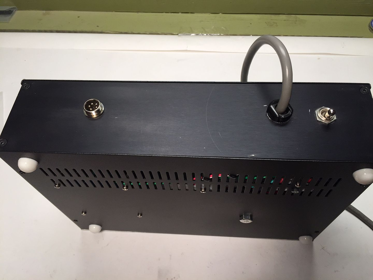
can you describe how did you set your Earth ground? Just personal curiosity. As far as I know, way one is to insulate TT ground and RCAs from its enclosure and to connect FSP box to Earth via separate wire in umbilical cord. Way two is to connect TT ground to FSP enclosure (RCA still insulated) and not to use Earth Ground on FSP box.
Sent from my iPhone using Tapatalk
Broadly similar in sound,
That's why my FSP boards and parts are still in their packaging. I'm having a hard time making the commitment of time and money just to make a sideways move.
Maybe i'll build it for my brother someday (or give him my Pearl II).
The in-circuit four LEDs current will be that of Q7's IDSS. So test Vf
...
snip
...
ccordingly. The Vf is measured across the LED only of course.
Understood ; I will use a lab supply with precise current settings and will set it to Q7's idss for getting the right combination of leds for 7.75V total drop . I just finished my supply and next days going to build the pre where i will need the leds.
Thanks so much all for the nice explanations and guidance. It is teaching a lot.
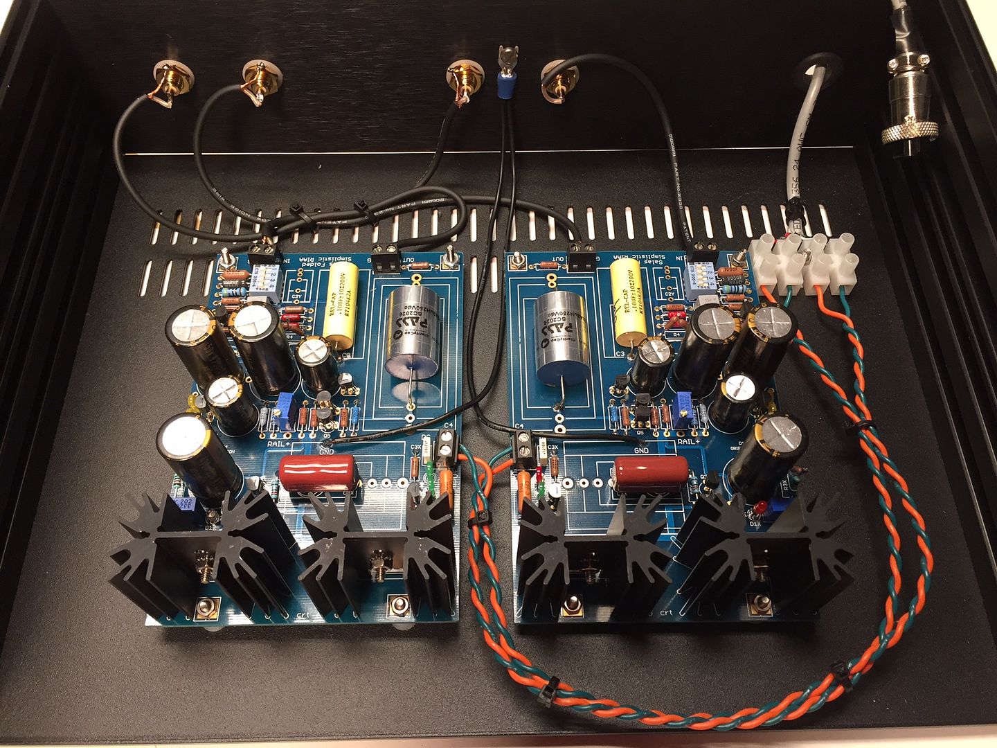
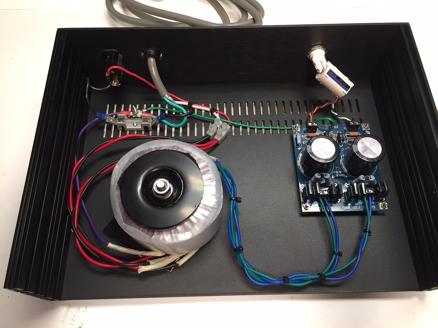
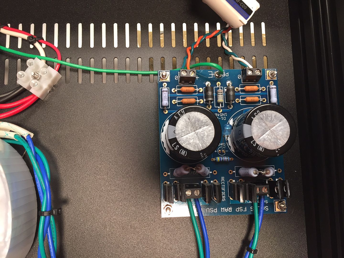
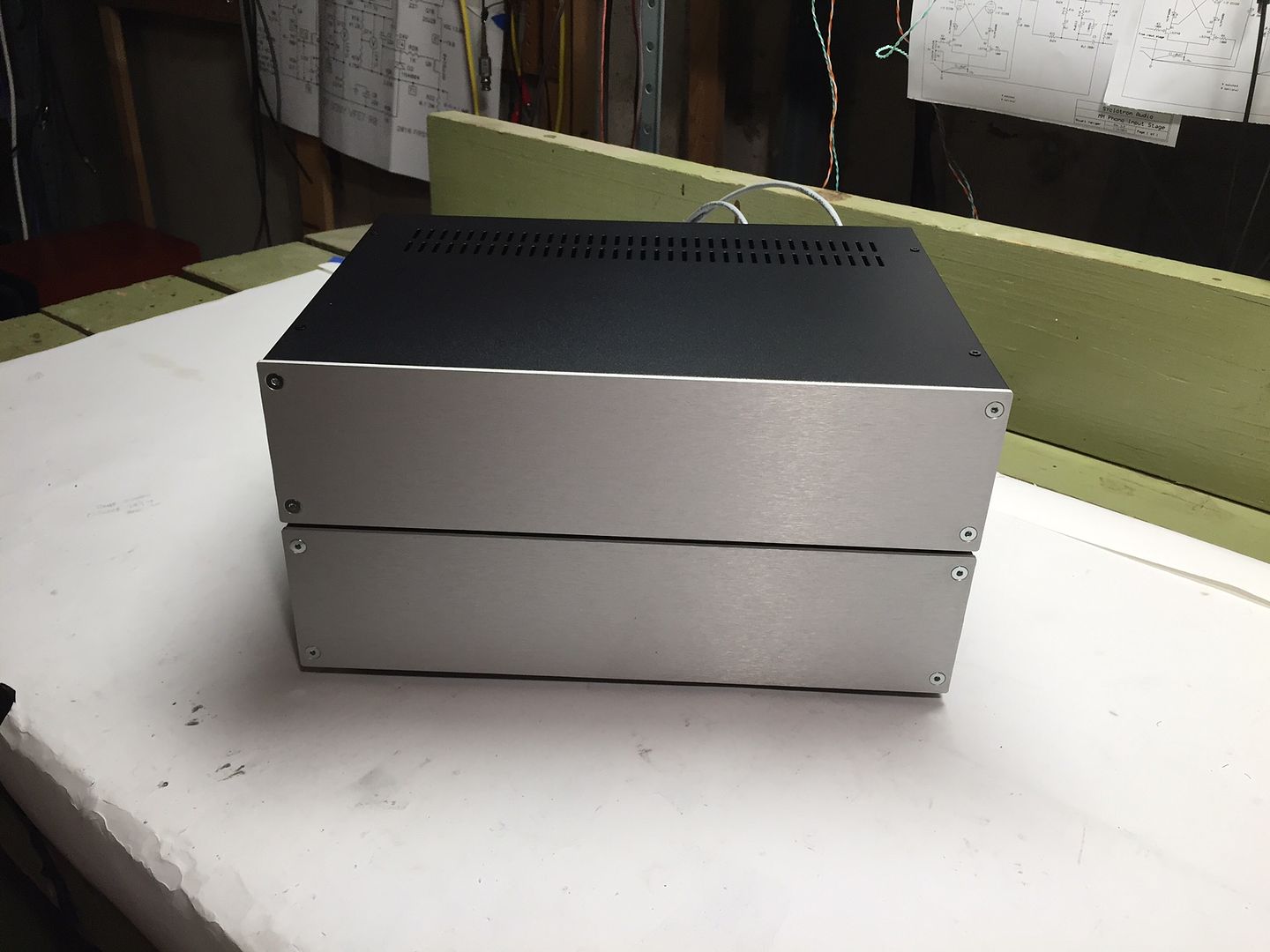
I will try to post some pics if anyone interested in a different look and flavor of your nice pre-amp.
That's why my FSP boards and parts are still in their packaging. I'm having a hard time making the commitment of time and money just to make a sideways move.
Maybe i'll build it for my brother someday (or give him my Pearl II).
Takes a careful listen with an MC cart before deciding your favorite to keep because the two designs have different approaches in areas and parts that tend to highlight more as the input signal becomes weaker.
Understood ; I will use a lab supply with precise current settings and will set it to Q7's idss for getting the right combination of leds for 7.75V total drop . I just finished my supply and next days going to build the pre where i will need the leds.
Thanks so much all for the nice explanations and guidance. It is teaching a lot.
I will try to post some pics if anyone interested in a different look and flavor of your nice pre-amp.
You can also use your very Q7s destined for assembly as test JFET CCS. With 18V on the lab supply. And 20mA CC protection threshold for avoiding mishaps. Drain to +V, gate and source together, from there to the LEDs string top anode and from bottom cathode to PSU return. On a typical breadboard. That way you test LEDs total Vf in what exact conditions they will see when assembled. Easy to exchange as many samples as you like on a breadboard to test and match two JFET+LEDs arrays.
You can also use your very Q7s destined for assembly as test JFET CCS. ...
Great advice; done that and worked like a charm! I am almost finished; Will power up this weekend.
Thank you again!
This schematic is quite close to the schematic from me - go to first pdf in post #8 underI have Supreme Silver/Oil in mine at the output.
I have also used M-Lytic 500V on tubes. Good, a little trebly I think, but clean. Nippon Chemi-Con KMH 105 C are 90% that good at much lower prices.
Your both channels work OK now? Finished?
Here is your specific shunt reg, attached.
http://www.diyaudio.com/forums/anal...ences-between-mark-levinsons-jc-1-jc-1dc.html
Which feature in this topology is most important for best results while listening test ?
Thank you for your advice.
I wouldn't say quite close, rather relatives in operational blocks system IMHO. C1,C2,C6,C7 are your most influential I would suppose by looking in your PSU schematic. My schematic you linked is the oldest so better look into SSLV1.1 version which had evolved from there. There are also analytic PDF instructions etc. for it. The Vref noise filtering capacitor and the termination Zobel's capacitor are always the more influential passive components in such a topology.
http://www.diyaudio.com/forums/power-supplies/192625-sslv1-1-builds-fairy-tales.html
http://www.diyaudio.com/forums/power-supplies/192625-sslv1-1-builds-fairy-tales.html
Hi Salas,
I am building an MM version. I have 52V per channel from the power supply board into 470R load resistors. The RD Link resistors are 10R. Is that voltage too high for the MM version? or should I increase the RD link resistors to get below 50V?
Thanks in advance,
David
I am building an MM version. I have 52V per channel from the power supply board into 470R load resistors. The RD Link resistors are 10R. Is that voltage too high for the MM version? or should I increase the RD link resistors to get below 50V?
Thanks in advance,
David
- Home
- Source & Line
- Analogue Source
- Simplistic NJFET RIAA