Math for computing Thermal Distortion
The size of the ThermalMass affects speed only, in a simple Rthermal & Cthermal model.
Lets compute the amplitude of the ThermalDistortion. The arithmetic is straight forward.
Assume 1milliVolt deltaGate into NJFET, with gm of 0.02 (1/50 ohms).
The deltaCurrent is 1mV/50ohm = 20 microAmps.
Somewhere, buried in my simulator menus, is the VDD value of 5 volts.
(yes, Salas topo probably uses 10 or 15 or 20 volts, cascade or not).
The deltaPower is deltaI * Vdrain_source = 20uA * 5v = 100 microWatts.
Our Rthermal (assumed a lumped R, and not the actual distributed mess) is 100 degreeC / watt.
Just multiply 100 microWatts * 100 degreeC/Watt, to get 0.01 degreeC change in the NJFET channel temperature.
At 1,000 microvolts/degC Temperature Coeff (shown in prior post), the change in Vgate is 0.01degC * 1,000uV/degC, or 10 microVolts. Against an input of 1mV or 1,000uV.
Thus a 1 millivolt input signal causes 10uV/1000uV or 1% bump; or -40dB.
This ratio is preserved for 250uV input. RMS versus PeakPeak also affects numbers.
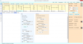
This attachment shows the 2SK170 shoehorned into an OpAmp stage.
The size of the ThermalMass affects speed only, in a simple Rthermal & Cthermal model.
Lets compute the amplitude of the ThermalDistortion. The arithmetic is straight forward.
Assume 1milliVolt deltaGate into NJFET, with gm of 0.02 (1/50 ohms).
The deltaCurrent is 1mV/50ohm = 20 microAmps.
Somewhere, buried in my simulator menus, is the VDD value of 5 volts.
(yes, Salas topo probably uses 10 or 15 or 20 volts, cascade or not).
The deltaPower is deltaI * Vdrain_source = 20uA * 5v = 100 microWatts.
Our Rthermal (assumed a lumped R, and not the actual distributed mess) is 100 degreeC / watt.
Just multiply 100 microWatts * 100 degreeC/Watt, to get 0.01 degreeC change in the NJFET channel temperature.
At 1,000 microvolts/degC Temperature Coeff (shown in prior post), the change in Vgate is 0.01degC * 1,000uV/degC, or 10 microVolts. Against an input of 1mV or 1,000uV.
Thus a 1 millivolt input signal causes 10uV/1000uV or 1% bump; or -40dB.
This ratio is preserved for 250uV input. RMS versus PeakPeak also affects numbers.
This attachment shows the 2SK170 shoehorned into an OpAmp stage.
Attachments
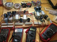
PSU breadboard for pre with FSP
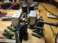
Beginning to settle on iron and stuff for my dac/riaa/volume/select/buffer box. From left to right
")
Any comments, something I have overlooked?
Beginning to settle on iron and stuff for my dac/riaa/volume/select/buffer box. From left to right
2x15 120 VA to CLC giving some 2x19,5 ripple free volts for the DCB1 at dummy load 2x325 mA.
2x18 2x18 80 VA to CLC giving 2x23,5 V for SSLV prereg to 2x15 V USB DAC at dummy load 2x320 mA.
7,5 V that is going to be RC:ed down to some 9 VDC for LM317 5,1 V DAC digital, 7805 for Muses volume chip digital and darlington collector signals for relays.
12 V giving some 16-17 VDC for 7812's feeding the relay coils (will have a few here and there).
Dual 36 V 30 VA CLC (RD/LINK 8 ohm) to some 2x48 V not so raw DC anymore.
Any comments, something I have overlooked?
Attachments
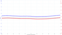
Little ripple for raw, very manageable. I remembered some old post in the Ref-D builds thread about pre-reg choices care for DAC's digital part while having local LDO's already. But it should always be a case by case study. http://www.diyaudio.com/forums/power-supplies/261031-reflektor-d-builds-16.html#post4070364
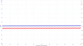
Yes looks good. I now remember that I did load the DAC once and got this answer. This is with the OPA shield, I now have the more current consuming discrete one on. So I guess Sonny is taking the sensitive parts of digital feed from the super regulated analog positive rail. The 5,1 probably takes care of less important stuff and I cant think it consumes many mA. Did you have a better option then 317? There is display options etc, dont know what it is used for without it. Must ask. Or measure.
Understanding SPECTRA of Thermal Distortion
Tho heating, in transistors, ICs, or resistors or PCBs can be very rapid (GHz or THz), the mass will average the heating changes and delta_Temperature will not appear, UNLESS VERY SLOW. Silicon and copper and resistor Tau, for 1micron sizes, is about 10 nanosec (NANO), but are not quite the same.
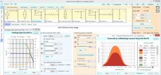
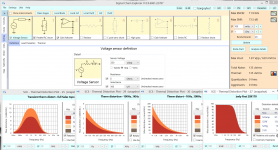
Here I examine 4 different ThermalDistortion plots. The first 3 are of entire Salas topology shoehorned into the simulator.
Lets examine the 3 plots on the left.
First is 0.1Hz to 10KHz, showing the several DCblock filters in Salas, as well as the RIAA rolloff starting at 50Hz + the ThermalTau at about 130Hz.
2nd from left is just 100Hz ... 1,000Hz; you'll see the distortion is smaller and continuing to drop off, but not going to zero.
3rd from left is just 1Khz...10KHz; you'll see the distortion is smaller yet and continuing to drop off, but not going to zero.
Rightmost plot is Thermal Dist of just the first 2SK170 gain stage. There is no DCblocking in that, so all the frequency content appears, down to DC.
What does this mean? The 2SK170 distorts the input sin wave, particularly if a SLOW sin wave. If this distortion involves the transconductance, then stage gain will also change, and all frequencies will be AM modulated.
Tho heating, in transistors, ICs, or resistors or PCBs can be very rapid (GHz or THz), the mass will average the heating changes and delta_Temperature will not appear, UNLESS VERY SLOW. Silicon and copper and resistor Tau, for 1micron sizes, is about 10 nanosec (NANO), but are not quite the same.
Here I examine 4 different ThermalDistortion plots. The first 3 are of entire Salas topology shoehorned into the simulator.
Lets examine the 3 plots on the left.
First is 0.1Hz to 10KHz, showing the several DCblock filters in Salas, as well as the RIAA rolloff starting at 50Hz + the ThermalTau at about 130Hz.
2nd from left is just 100Hz ... 1,000Hz; you'll see the distortion is smaller and continuing to drop off, but not going to zero.
3rd from left is just 1Khz...10KHz; you'll see the distortion is smaller yet and continuing to drop off, but not going to zero.
Rightmost plot is Thermal Dist of just the first 2SK170 gain stage. There is no DCblocking in that, so all the frequency content appears, down to DC.
What does this mean? The 2SK170 distorts the input sin wave, particularly if a SLOW sin wave. If this distortion involves the transconductance, then stage gain will also change, and all frequencies will be AM modulated.
Attachments
keantoken:That is real interesting. How do you know the time constant of the thermal distortion?
The thermal time constants of copper and of silicon are determined by computing the thermal capacity of a cubic meter of the material, and by computing the thermal resistance of a cubic meter of the material. Then multiply the R times the C, to produce TimeConstant. In the physics books, the inverse value is shown, labled ThermalDiffusivity.
For silicon, ThermalTau TimeConstant is 11,400 seconds.
For copper, its 9,000 seconds.
These numbers scale down, for 0.1Meter and 0.01Meter and 0.001Meter cubes of material, etc etc. We've just built the scaling into worksheets, used to model pure discrete R*C (not distributed R,C) lowpassfilters.
Attachments
Power Line magnetic coupling into Phono/RIAA Preamp
Sometimes that 60Hz (or 120Hz hum, or buzz, or singing) gets into the music. Why? And what is to be done?
Here, in the discrete 2-stage topo, we quite by accident couple FROM THE WALL WIRING 4 inches away from 1meterlong non-twisted-pair between the cartridge and the shunt/gainstage#1. How bad is it? and whats to be done?
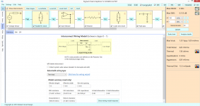
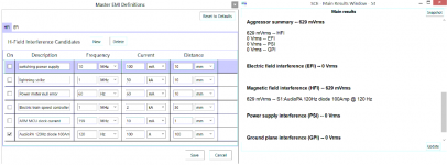
The first attachment shows the Salas topology, with inter-component wiring that is vulnerable to magnetic fields. [to model this, you gotta turn on the "Gargoyles", the "HFI", and the "I/C"; also you create a new magnetic interferer of 120Hz at 100Amps, distance of 0.1meter 100mm 4"]. Result? Look on lower right and see 629mRMS aggressor. In the AnalysisResults, part of attachment#2, we read that comes from the non-twisted-pair (the twin-lead) between Stage0 MovingCoil250uVpp and the Stage1 ParallelRCShunt.
What is to be done?
1) when you get that house built, have the electrician use combined hot/rtn/safety cable, so the hot/rtn are at most 1/2" apart and the magnetic fields mostly cancel; if separate 12gauge wires are used, we get the problem here
2) have the cable, with 1/2" between hot/rtn, oriented parallel to the wall so the magnetic flux from hot and from RTN are the same distance to whats inside the room (but you'll have no say in this)
3) use twisted pair from cartridge to PreAmp
4) use powerline filters to prevent rectifier/diode surges atop the sine waves [cheap microwave ovens, with little if any filtering, are a big problem because they need 2,000 watts and they use 2,000 volts into the rectifiers with enormous slewrates and diode-turnontimes much faster than in your 50volt Audio PA]
5) you favorite method here
Sometimes that 60Hz (or 120Hz hum, or buzz, or singing) gets into the music. Why? And what is to be done?
Here, in the discrete 2-stage topo, we quite by accident couple FROM THE WALL WIRING 4 inches away from 1meterlong non-twisted-pair between the cartridge and the shunt/gainstage#1. How bad is it? and whats to be done?
The first attachment shows the Salas topology, with inter-component wiring that is vulnerable to magnetic fields. [to model this, you gotta turn on the "Gargoyles", the "HFI", and the "I/C"; also you create a new magnetic interferer of 120Hz at 100Amps, distance of 0.1meter 100mm 4"]. Result? Look on lower right and see 629mRMS aggressor. In the AnalysisResults, part of attachment#2, we read that comes from the non-twisted-pair (the twin-lead) between Stage0 MovingCoil250uVpp and the Stage1 ParallelRCShunt.
What is to be done?
1) when you get that house built, have the electrician use combined hot/rtn/safety cable, so the hot/rtn are at most 1/2" apart and the magnetic fields mostly cancel; if separate 12gauge wires are used, we get the problem here
2) have the cable, with 1/2" between hot/rtn, oriented parallel to the wall so the magnetic flux from hot and from RTN are the same distance to whats inside the room (but you'll have no say in this)
3) use twisted pair from cartridge to PreAmp
4) use powerline filters to prevent rectifier/diode surges atop the sine waves [cheap microwave ovens, with little if any filtering, are a big problem because they need 2,000 watts and they use 2,000 volts into the rectifiers with enormous slewrates and diode-turnontimes much faster than in your 50volt Audio PA]
5) you favorite method here
Attachments
That looks like an interesting program, sort of like an automated back-of-the-envelope calculator. It seems to fill in some gaps between simulator and prototype.
Yes indeed give us a copy please
- Home
- Source & Line
- Analogue Source
- Simplistic NJFET RIAA