FSP mod for MM with output 3.5mV
Salas I want to use the FSP for MM Shure V15 III with output 3.5mV, FSP build guide advice is "for circa 5mV of output MM cart don't populate Q2, R3, use 91R R2, 5.6K 1W R13, 1.8K R4 for 40dB" I would prefer to have 45dBs or a little more, is possible?
TIA
Felipe
Salas I want to use the FSP for MM Shure V15 III with output 3.5mV, FSP build guide advice is "for circa 5mV of output MM cart don't populate Q2, R3, use 91R R2, 5.6K 1W R13, 1.8K R4 for 40dB" I would prefer to have 45dBs or a little more, is possible?
TIA
Felipe
Salas I want to use the FSP for MM Shure V15 III with output 3.5mV, FSP build guide advice is "for circa 5mV of output MM cart don't populate Q2, R3, use 91R R2, 5.6K 1W R13, 1.8K R4 for 40dB" I would prefer to have 45dBs or a little more, is possible?
TIA
Felipe
Use the 43dB configuration parts values from the guide. More than 43dB gives somewhat high THD for a 3.5mV cartridge and its dangerous to overload at clicks and pops. Its already 1mV more than High MC average which 43dB works fine with.
Just builded one from gb and I have to really thanks Salas and Tea for make this great phonostage available. It's ourtstanding performer and value. I have compared it with some others projects and it performed surpruising well.
Congrats, you are welcome. If you want to share pictures or more info on your test system and references, surely we other members will be pleased to know.
I'm designing the back panel for my FSP and I can't decide between these two options:
I would believe that the one with the DC input in the middle is preferable as I can have shorter internal wiring, but the one with DC on one side and RCA makes the outside cabling better manageable.
An externally hosted image should be here but it was not working when we last tested it.
An externally hosted image should be here but it was not working when we last tested it.
I would believe that the one with the DC input in the middle is preferable as I can have shorter internal wiring, but the one with DC on one side and RCA makes the outside cabling better manageable.
I'm designing the back panel for my FSP and I can't decide between these two options:
An externally hosted image should be here but it was not working when we last tested it.
An externally hosted image should be here but it was not working when we last tested it.
I would believe that the one with the DC input in the middle is preferable as I can have shorter internal wiring, but the one with DC on one side and RCA makes the outside cabling better manageable.
I would go with any layout that reduces the signal path giving the shortest signal wiring. As Salas said, the DC wiring can be slightly longer.
Rush
TP1 TP2 low
Hi
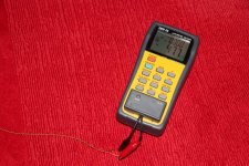
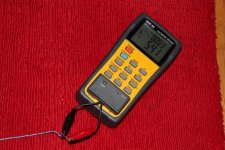
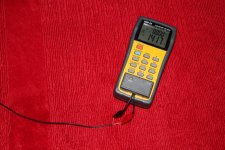
I had both the rails at 35 volts and TP1-TP2 at around 0.6v.
I adjusted the potentiometers to the end of their ranges so that the rails at now 32.6 v and TP1-TP2 about 2.6 volts. I have the full gain circuit.
Which component do I need to change to bring TP1-TP2 to 3.6v please?
I will post photos soon.
Barry
Hi guys,
FWIW I did a little cable capacitance compair today. Posted it here because its for internal use to my FSP/Pre build and cables are often up here. I twisted (very tedious) 118 cm of 32 AWG (very thin 0.0320 mm2) MIL speced PTFE insulated silver coated copper cable from Alpha Wire. Then I compared that to my regular thin coax, Belden NFR 0801 avr 100 pF/m and a cat5 twisted pair, known for low capacistance for HF use, Those were also cut to 128 cm length. Here are the results:
Twisted 32 AWG 47,7 pF
Cat 5 54,1 pF
Belden coax 141,5 pF
Recalculated to pF/m:
Twisted 32 AWG 37,2 pF/m
Cat 5 42,3,1 pF/m
Belden coax 110,5 pF/m
Attachments
Last edited:
Sensible values findings and useful info especially to MM carts guysHi guys,
FWIW I did a little cable capacitance compair today. Posted it here because its for internal use to my FSP/Pre build and cables are often up here. I twisted (very tedious) 118 cm of 32 AWG (very thin 0.0320 mm2) MIL speced PTFE insulated silver coated copper cable from Alpha Wire. Then I compared that to my regular thin coax, Belden NFR 0801 avr 100 pF/m and a cat5 twisted pair, known for low capacistance for HF use, Those were also cut to 128 cm length. Here are the results:
Twisted 32 AWG 47,7 pF
Cat 5 54,1 pF
Belden coax 141,5 pF
Recalculated to pF/m:
Twisted 32 AWG 37,2 pF/m
Cat 5 42,3,1 pF/m
Belden coax 110,5 pF/m
Twisted pair is alright when there is no benefit in noise pick up compared to shielded coax. Its all a matter of interference clean position of use. In general the coax is more secure when the signal level is very low. For MC carts the extra pF would not play a role anyway.
My sfps has started fading on o e channel after around 2 hours of use. The stereo image slowly moves from centre to the left, there is always some output from the right speaker but it is fairly minimal.
Switch off for 10 minutes and it's ok again. Any ideas where to start fault finding?
Switch off for 10 minutes and it's ok again. Any ideas where to start fault finding?
Did you tweak VR1 pots also? If you already did to no avail you could use a smaller value R3x.
Hi Salas
Yes I tried
Hello Barry
One thing is you got 9 ma (circa) K369s. Not of dubious origin I hope. Such IDSS asks for less rail voltage than usual. Smaller R3x should extend your minimum adjustment threshold.
The fading thing maybe is temperature build up that changes the cascode BJT bias. Which maybe is wanting already. I suggest you finally adjust TP by monitoring with crock extensions after half an hour or more with the lid on.
One thing is you got 9 ma (circa) K369s. Not of dubious origin I hope. Such IDSS asks for less rail voltage than usual. Smaller R3x should extend your minimum adjustment threshold.
My sfps has started fading on o e channel after around 2 hours of use. The stereo image slowly moves from centre to the left, there is always some output from the right speaker but it is fairly minimal.
Switch off for 10 minutes and it's ok again. Any ideas where to start fault finding?
The fading thing maybe is temperature build up that changes the cascode BJT bias. Which maybe is wanting already. I suggest you finally adjust TP by monitoring with crock extensions after half an hour or more with the lid on.
Understand.
I kind of expected if would be q-1 or 2. I've got 2 spare 170s, but only one in range, So, unless I order more, I'll have to re-install any 170s that don't test bad.
I replaced q1, q2, c3, q4, then got sidetracked for a couple of weeks. Got back to it today, replaced q5 and it now plays. However, I've got different (inferior) sound on the previously bad board. I had bought a matched quad set of sk369 from tea bag, so that should be ok. Just sent him a pm to see about 170s.
I'll keep after it and let you know when it's back in shape.
Thanks
So it was at the output stage after all. There is R11 and the voltage drop across it indicates the current pulled by the output buffer stage. Q5 IDSS determines that pull. You can compare R11 drops between channels. If its a randomly higher IDSS Q5 than Q6 IDSS it can saturate Q6. Q5 should have either equal or bit less the IDDS of Q6.
- Home
- Source & Line
- Analogue Source
- Simplistic NJFET RIAA


