And it takes patience in everything too not to screw it in the end, so wait for me to finish it off properly for PCB and I will be back. Because not very practical in its initial form factor
The tidiest lab bench I have ever seen
There is a Nos monolithic pair that I have found nice but I put modern LSK monolithic stuffing option too, a single easy to get Jfet, two easy to get enhancement Mosfets and a fairly easy to get depletion one. All of those took many iterations both for circuitry configurations and types until I got satisfactory good measurements with the least possible semis. There is a DC servo op-amp too for drift safety although it hardly works because the system nulls well with a single trimmer.
Talking about measurements here are samples from the non solicited and initially oscillating general purpose matrix board quick layout of my friend that I left him do what he may on purpose so to check how it stands in the building hands of others when having no learned info about how it works and no CAD boards. It took me only an hour to debug it for him.
Attachments
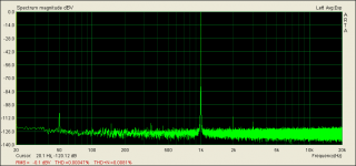
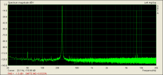
Those are the normal operating 1kHz 2.83V pk-pk output THD % and 250Hz 8kHz IMD SMPTE % charts of that build. IMD SMPTE is kind of acid test on how clean an amp will be in complex music replay. When a big low frequency signal exists along a high frequency signal and those small spikes around the base of the high frequency signal show how much the bass one it can modulate it. If a drum or bass guitar plays along with a flute how much the drum will make the flute waver for instance. A bit of 50Hz mains spike possibly from those many unshielded EI transformers or it could have had better wiring. But the small spikes around 8k are the 250Hz modulation and its harmonic. The oscillations were typical wiring and compensation matters that got easily fixed using the scope before the FFTs were done.
P.S. In #16139 you could also see how an IMD SMPTE test looks on the scope. The low frequency sinewave has the high frequency zig zag riding on it.
P.S. In #16139 you could also see how an IMD SMPTE test looks on the scope. The low frequency sinewave has the high frequency zig zag riding on it.
Interesting video with a couple of large scale AT ART 1000 weird coils cart mock models showing the inner build. Thanks to Vgeorge for the link.
https://www.youtube.com/watch?v=PaoA4ZuGlOw#t=194
https://www.youtube.com/watch?v=PaoA4ZuGlOw#t=194
Coils right at the tip is odd. I would have named it Moustache 1000 or Hipster 1000. Salvador Dali would have bought one if aliveIt may be big but it's very quiet.
On the one hand putting the coils there seems like sacrificing the mechanical advantage of the cantilever. OTOH it's kind of like the Decca "direct tracing" carts. Flexure of the cantilever is unimportant since the coils follow the stylus exactly. But at 5K Euros it's an order of magnitude out of my league.
Interesting video with a couple of large scale AT ART 1000 weird coils cart mock models showing the inner build. Thanks to Vgeorge for the link.
https://www.youtube.com/watch?v=PaoA4ZuGlOw#t=194
More:
http://www.analogplanet.com/content/audio-technicas-evolutionary-new-art1000-phono-cartridge#KciwqpxzqU0cQJt1.97
https://www.youtube.com/watch?v=PaoA4ZuGlOw
Last edited:
Just starting Salas Folded Simplistic RIAA build
I just received boards and mini kits I bought from another member here. I'm excited the start this build.
I would like to use the Vishay naked Z foil resistors in the R1 and R14 positions, as you know they are pricey. I'm thinking of setting the preamp up for 100R input loading which what is the spec. for my cartridge. So I would make R1 100R and leave out Rx1 - Rx4, and the DIP switch, is this correct.?
Unhappy marriage
I finished my build late last year (last post #15548); and the FSP has been delivering great sound. I decided to try my hand at building a 6SN7 tube pre. That's now in the cake pan stage and has been making superb digital sound for about a week. This morning, I hooked it up to the vinyl side. My AT ART9 started jumping around and chattering. I screwed around with it too long and now there is no output and it's probably damaged. I tried it again with a Denon DL-301-ii, which, like the ART9, started chattering and jumping around; but, I stopped that test immediately and the denon seems to be ok. Both carts worked properly with my Mcintosh c-27. (I know, should have tried the denon first; but I didn't expect an issue.)
Anyway, that's my problem. But it seems pretty likely that the FSP and the 6SN7 are not going to be happy together until something gets modified. So, I'd sincerely appreciate ideas on what I should be checking into - on either piece. I can post some specifics on the pre if appropriate.
Thanks,
- Home
- Source & Line
- Analogue Source
- Simplistic NJFET RIAA