Andrew, nice idea! We can use lets say 100R for R6x and 100r trimmer in parallel. By trimmer we can have whatever LEDs installed as far as they are above 1.8Vf. Then we can set Vf by trimmer to whatever we need and match L/R channels precisely. Hopefully Borns 3296 can operate at that level of input DC.
Sent from my iPhone using Tapatalk
Sent from my iPhone using Tapatalk
If you also got Vgs matched Q1xs only then it makes perfectionism sense. In my prototype I had matched leds and Q2xs idss only. Though by chance both channels Q1x CCSs draw the same current as far as my lab PSU indicates. It amounts to nothing consequential if it is say 10% out between channel regs but just mentioning since it looks like you would enjoy the study of matching them perfectly. So put your lab PSU in series mode set for 24V+24V, + appears on extreme red binding post - on extreme black, check you got 48VDC and the polarity using your DMM because excess voltage or polarity error when connecting to DCin FSP equals boom-smoke. Set 200mA CC mode, press OFF on lab PSU power out, make the connections to FSP DCin first channel, press power ON to read current draw on its panel meter as if the lab PSU was one output of your raw board. It should take a couple of minutes to settle. Shut down & repeat for the other channel. You should read 90-110mA for each one channel's draw.
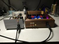
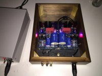
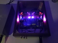
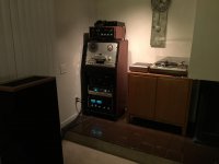
My FSP build is – for the time being – complete. I’ve enclosed a couple of pics including a “Stealth” shot for Salas. The power supply fits in the stack behind the tape deck. You can see a couple of Vishay z-foil resistors “standing tall” in the impedance circuits. That was to facilitate an A/B listening test with and without z-foils in place. (My present cart is a Denon dl-301ii, which I think does best at 330 ohms; so I installed a 330r z-foil in rx1 and a Takman Rey in rx4 to allow for quick switching.)
I had a couple of serious audio people in to evaluate the FSP and opine on the z-foils. At that time I probably had about 20 listening hours and about 40 power-on hours. Everyone was highly impressed with the clarity, detail, soundstage, and overall performance of the FSP. Interestingly, over the couple of hours we listened, the sound quality actually increased.
Without question, the z-foils impact sound . Detail is increased across all frequency ranges. I had read reviews (mostly by z-foil vendors) of the benefits of this resistor; but, in this case, the reviews were accurate. As to value for the price, if you were building a USD 200 soundstage, you would probably want to think twice about spending USD 15-20 for a resistor. But, there was no question in any of my listener’s minds about the sonic impact – and monetary value - of z-foil resistors in the FSP.
I’m in the market for an up graded cart. Until now, Ortofon Quintet Black and AT33sa had been the primary contenders, but I continue to read rave reviews about the AT ART9. Without getting too far away from this thread, I wonder if anybody has views on that cart. I’m concerned its high compliance (18 x 10 – 6 cm / dyne (100 Hz)) and my 16g, Grace 940 tonearm.
I am going to postpone installing the rest of the z-foils until I have the new cart and have determined what impedance setting I want. Also, as to C2Y, I don’t notice any loss of high end response, but, again, I’ll wait until the new cart is on-hand before worrying about that.
Attachments
I own an AT-ART 9 and couldn' t be happier. If you can afford it, go ahead and get it. You should stretch your budget to 3000 usd to get something better I think.
Resolution and neutrality is top notch.
Forgot to mention, I use an SME IV arm. I do no think you are going to have a problem with the mass of your arm, only a little lower resonance point.
Nice build! And yes z-foils make a difference at least in cartridge loading in this phono.
Resolution and neutrality is top notch.
Forgot to mention, I use an SME IV arm. I do no think you are going to have a problem with the mass of your arm, only a little lower resonance point.
Nice build! And yes z-foils make a difference at least in cartridge loading in this phono.
Last edited:
If you also got Vgs matched Q1xs only then it makes perfectionism sense. In my prototype I had matched leds and Q2xs idss only. Though by chance both channels Q1x CCSs draw the same current as far as my lab PSU indicates. It amounts to nothing consequential if it is say 10% out between channel regs but just mentioning since it looks like you would enjoy the study of matching them perfectly. So put your lab PSU in series mode set for 24V+24V, + appears on extreme red binding post - on extreme black, check you got 48VDC and the polarity using your DMM because excess voltage or polarity error when connecting to DCin FSP equals boom-smoke. Set 200mA CC mode, press OFF on lab PSU power out, make the connections to FSP DCin first channel, press power ON to read current draw on its panel meter as if the lab PSU was one output of your raw board. It should take a couple of minutes to settle. Shut down & repeat for the other channel. You should read 90-110mA for each one channel's draw.
Hi Salas,
Yes, and it is related to my perfectionism more than to anything else. I just wonder how much my Vf change by R6x tweaking under real condition. Unfortunately, my PSU is 36V (18+18) max and I can't use it for the real condition simulation. It is not an issue since I'll measure Vf on LEDs when all will be assembled and connected to the original Phono PSU. Then I'll see R6x dependency. BTW, I'm thinking about nice and simple PSU purchase. Will you recommend something like HP E3617A? It is 60v 1A (60W). I see nice looking units on eBay now.
Also, I went to Selectronics (France) and purchased two R-Core 120VA (2x120V primary, 2x18V secondary) transformers made by Shilchar. They arrived yesterday damaged. Box was trashed to pieces (very thin cardboard used for such heavy load) and one trany has a broken bobbin insulator. Little mess...
Another issue that it is no datasheet came with it. It is multi-output setup and it took me a while to figure out who is who. Does anyone did find some datasheet for these tranys beside what I see on Shilchar site. None of those are matching my outputs. I have 10 colored outputs wires (2x Bck+Rd, and 2x Yel+Blu) with about 20V (with no load) and 2 white (1 coming from each bobbin side) wires that I have no clue what they are. Infinity residence between Wh+Wh and I thought it might be a screen, however I see about 10V when trany is connected to AC. Very strange.

Sent from my iPhone using Tapatalk
Happy Xmas to all
thanks to Nick for this endless thread
+1
I reported my findings on these 230:18+18Vac Rcore.Hi Salas,
Yes, and it is related to my perfectionism more than to anything else. I just wonder how much my Vf change by R6x tweaking under real condition. Unfortunately, my PSU is 36V (18+18) max and I can't use it for the real condition simulation. It is not an issue since I'll measure Vf on LEDs when all will be assembled and connected to the original Phono PSU. Then I'll see R6x dependency. BTW, I'm thinking about nice and simple PSU purchase. Will you recommend something like HP E3617A? It is 60v 1A (60W). I see nice looking units on eBay now.
Also, I went to Selectronics (France) and purchased two R-Core 120VA (2x120V primary, 2x18V secondary) transformers made by Shilchar. They arrived yesterday damaged. Box was trashed to pieces (very thin cardboard used for such heavy load) and one trany has a broken bobbin insulator. Little mess...
Another issue that it is no datasheet came with it. It is multi-output setup and it took me a while to figure out who is who. Does anyone did find some datasheet for these tranys beside what I see on Shilchar site. None of those are matching my outputs. I have 10 colored outputs wires (2x Bck+Rd, and 2x Yel+Blu) with about 20V (with no load) and 2 white (1 coming from each bobbin side) wires that I have no clue what they are. Infinity residence between Wh+Wh and I thought it might be a screen, however I see about 10V when trany is connected to AC. Very strange.
Sent from my iPhone using Tapatalk
http://www.diyaudio.com/forums/parts/283421-selectronic-rcore-transformer.html#post4538077
They are terrible in that they have been wound to the wrong voltage and one came without any labeling. Selectronic should be hung, drawn and quartered for selling this quality of product.
Now that I know I have don't have a 230:18+18Vac transformer, but is nearer 234:22.6+22.6Vac unloaded, I can make allowance for the excess voltage delivered to the PSU.
When used on my typical 245Vac Mains supply, the unloaded secondary voltage will be around 23.6Vac, instead of ~20.7Vac for a 15% regulation 18Vac transformer. That's ~ 14% overvoltage compared to the advertised voltage rating.
Last edited:
Hi Andrew, I find its that winding orientation in hard way. I connected primary as classic knowledge say and had a Buzzz. Connected 2 pairs W to Bl and it works for 120v. Do you see two short white wires on secondary too? What they are?
Sent from my iPhone using Tapatalk
Sent from my iPhone using Tapatalk

My three, 2 @ 30VA and 1 @ 120VA have different windng taps. All three are identical. That let me wire the unlabeled 120VA in the same way as the two labeled 30VA.
But the phase of the windings is VERY non standard.
Each half limb has a primary and two secondaries on it.
Both windings are wound identically. But because they get assembled facing in opposite directions, the two sets of windings are effectively out of phase.
This means that if you want to connect the two 117Vac primary windings to 110/120Vac you need to wire opposite end taps to the Live and the other end taps go to Neutral. There is no documentation with the Rcore to explain this.
Primary: 117Vx2 Bleu/Noir
So one Blue from one side and one White from the other side go to Live
The spare Blue and White go to Neutral. Use a Mains Bulb Tester to test this. A Variac does not give effective protection from damage. Mine too HUMMED when I connected to the Variac and I wound it up to past 20Vac. I did not hear that as the warning that I got it wrong. I kept going to 40Vac and by now the hum was quite loud. OOPS !!!! Just 16% of nominal voltage from the Variac and my transformer was in trouble.
I have the 4 secondary taps from each winding and a white. This white is electrically isolated from all other taps. Check your white is also electrically isolated. This should be the Electrostaic Screen
My label states:
Ecran électro-statique: Masse Noir
Last edited:
Some time ago, when I was considering to back-up all my vinyl to digital, I almost bought a Korg MR2 portable recorder. It seemed a reasonable solution in price/performance ratio. You can use it as a standalone device storing your recordings in a SD card. Output formats are PCM (up to 192kh/24bit) and 2.8Mh DSD. Even -God forbid !  - compressed mp3.
My vinyl-to-digital project was delayed for a number of reasons. I never bought the Korg and I have no direct experiences on the real performances of the device. Maybe somebody here owns, or has owned, one of these and is able to enlighten us
- compressed mp3.My vinyl-to-digital project was delayed for a number of reasons. I never bought the Korg and I have no direct experiences on the real performances of the device. Maybe somebody here owns, or has owned, one of these and is able to enlighten us
- Home
- Source & Line
- Analogue Source
- Simplistic NJFET RIAA