Hi! I see many people on this thread and others that need to match BJT transistors, FETs or other important components for their build.
You could be interested to own this little tester below, or equivalent, to help with the job. There are many sellers and other older models available on eBay. I do not recommend any particular one, its up to you to do your shopping and select what suits you best, but may be Salas or someone else could make a recommandation to help us all.
I will simply say that I had an issue with "tianlo_go". He sent me a different tester from what I had paid for(lower grade, earlier model) and on top, it was defective.
I argued with this seller, but that didn't do anything good. He refused to replace or to refund the faulty tester.
I went then to PayPal, they juged the case in my favor and I finaly received a full refund from them.
Needless to say that my trust in this guy is nil and I would not like to see anyone of you caught in the same problems.
Wish you the best of luck and I will follow this thread to see what comes out with this suggestion.
NEW Transistor Tester Diode Triode Capacitance ESR Meter MOS PNP NPN | eBay
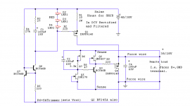
You may convert it to TO-220 with Q1 IRF9610 Q4 IRF9530. Q2 Q5 2SK117GR (Q5 5-6mA IDSS Q2 can be less). C2 220uF 50V add an LED between R7 and Q5 node. C4 50V. Make double mono.
I am going to put together the shunt. What value should I use for the trimmer at R6? I need 38V in and 28V out. The batteries are not lasting as long as I would like and the rail voltage is changing as the batteries wear.
Now for some listening impressions:
Mine is a 40db version on protoboard, good matched caps, powered by 20 "aa" batteries right now. Table is a Rega P5/Ortofon 2M bronze. Amp is an F5, preamp a BA-3. Speakers are Focal 714V. I have maybe 10 hours on the Salas phono so it's probably broken in, maybe not fully.
Honestly, this is a spectacular phono stage. It is fast, detailed and the imaging is really stable. Compared to my prior phono, a jfet "Le pacific"-style it has much more air and detail and the imaging is more stable and well placed. Little decays and the sound of the room is much more present. Vocals are more forward but in a good way. At loud listening levels (90+db) I am noticing a lot more clarity and lack of compression. The hi-end is more extended and smoother with less grain and strain. I love it.
I had a friend over the other day...he immediately noticed a difference in the system and usually doesn't care about such things. We've both spent a lot of time around music and playing music...we have good ears but it takes a major upgrade for a 3rd party who doesn't listen to your system regularly to notice a change. And immediately he was impressed.
Well done Salas. I can't wait to get the shunt up and running.
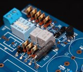
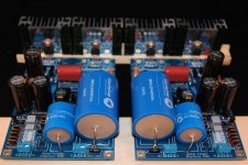
Attachments
You are using the special single K170 input MM 28V B+ schematic for those not having K369s if I remember correctly? Nice that you like it. When the needle wears out try upgrade the nose to nude Shibata Ortofon 2M Black status. It worths it.
If you have a pair of 5-6mA IDSS Q5 then 5K trimmer is alright as in the original schema. That is why I mentioned specific IDSS. You should get about 28V at half way.
If you got weak Q5s you can always make R7 higher value. Say 5.6K for 3-4mA Q5.
If you have a pair of 5-6mA IDSS Q5 then 5K trimmer is alright as in the original schema. That is why I mentioned specific IDSS. You should get about 28V at half way.
If you got weak Q5s you can always make R7 higher value. Say 5.6K for 3-4mA Q5.
You are using the special single K170 input MM 28V B+ schematic for those not having K369s if I remember correctly? Nice that you like it. When the needle wears out try upgrade the nose to nude Shibata Ortofon 2M Black status. It worths it.
If you have a pair of 5-6mA IDSS Q5 then 5K trimmer is alright as in the original schema. That is why I mentioned specific IDSS. You should get about 28V at half way.
If you got weak Q5s you can always make R7 higher value. Say 5.6K for 3-4mA Q5.
Yes, iam using the "roberto" schematic with 2sk170 input.
For q5 on the shunt I have some 8ma 2sk170. I guess a 5k trimmer will work?
Thanks again Salas.
P.S. Make two shunts, one per channel. Maybe with twin secondaries single trafo not necessarily fully separated double mono, but two rectifications & regs surely better stuff. Antek has cheap magnetcally shielded toroids accessible in the American market. AS-1228 model should not go over 40VDC at 120VAC wall power.
Yes, iam using the "roberto" schematic with 2sk170 input.
For q5 on the shunt I have some 8ma 2sk170. I guess a 5k trimmer will work?
Thanks again Salas.
Prefer K117GR for less voltage drift which is more important in the FSP that in the previous that this shunt was designed for. Don't need be matched. Get a few from Ampslab if you can. Don't forget the LED also, the one I recommended you to add. 8mA K170 will still work with 5K but in its short 1/5 range. Better make R7 1.6K-1.8K in this case.
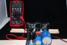
It does look like I am able to set the tp1-2 voltage to 3,6V fluctuating around +-0,05V. I do have to set VR1 to max clockwise and adjust with VR2 for that tho. Vin 48, current is 107 mA and rail som 32,3. No heatpaste yet, just poliched sink surfaces. Q6x sink gets hottish and Q1x sink warmish.
Am I on par?
Am I on par?
Attachments
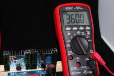
8mV variation in 3600mVdc is ~0.2%
That is good.
The output can move around by +-0.1% and the amp performance will not vary.
What is far more important is the dynamic impedance of the regulator output. That is determined by the design, not by the drift in voltage due to varying airstream.
That is good.
The output can move around by +-0.1% and the amp performance will not vary.
What is far more important is the dynamic impedance of the regulator output. That is determined by the design, not by the drift in voltage due to varying airstream.
Hi Salas,
I have many JFETs here, so I will test. I only have the defective unit on hand. I purchased a new one, it is on way now. It will take some time.
So far, it detects JFETs as you said, measures VGS but the current value is not good. I don't know exactly what and how the measurements are done. The final jugement will come with the new one.
I will continue over the weekend and will be back with the results.
That is not beyond your knowledge.
You have to take into account that its friday and its my kid free weekend
")
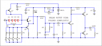
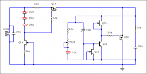
My schema is something like this:
LEDs dont seem so affected by outside temp. Q3x and Q4x is though. Q3x rises voltage on touch, Q4x lowers it.
Attachments
Last edited:
Are you using the 369 in the regulator, or in the RIAA?
Q4x has a -ve tempco for Vbe.
The output voltage is the SUM of (VbeQ4 + Vresistorstring)
As Q4x temp rises the output voltage goes down, because Vbeq4 goes down.
Q3x has either a +ve or -ve tempco depending on what device you chose and what current you chose to run through it.
The latest Qs become
What is Q3x and what current is passing through Q3x?
- Home
- Source & Line
- Analogue Source
- Simplistic NJFET RIAA