Re: my salas riaa pcb art
Hi Kent
Can you point your schematic please.. it seems the components have different numbers from my version..
Ricardo
kstlfido said:ikoflexer and all-
Here is the copper and top side art pdf's of my Salas Riaa board. I can almost visually walk through the circuit now! If someone can see mistakes, please let me know.
I gave the input cap C8 a hole next to the signal in terminal. Just tack the other end of the this cap to the ground plane.
Unzip and thou shall find 2 pdf's, both reversed ready for printing!
Hi Kent
Can you point your schematic please.. it seems the components have different numbers from my version..
Ricardo
Here it is. Only suggestion is that the right most JFET is better to face to the right so the g,s short together instead. The decoupling capacitors earth to the right needs an individual wire to the star, since Kent divided the signal return from the psu decoupling returns.
Attachments
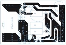
Thanks Salas. It looks like on J1 I got the orientation 'flat' backwards but the G and S are together, D goes to + rail.
Actually, I noticed some other inconsistencies now. Part numbering is a bit chaotic; and some redundant parts. I suppose it depends on which schematic you look at. I will get to these issues later this week. So, please do not use until I figure it out.
-Kent
Actually, I noticed some other inconsistencies now. Part numbering is a bit chaotic; and some redundant parts. I suppose it depends on which schematic you look at. I will get to these issues later this week. So, please do not use until I figure it out.
-Kent
kstlfido said:Thanks Salas. It looks like on J1 I got the orientation 'flat' backwards but the G and S are together, D goes to + rail.
Actually, I noticed some other inconsistencies now. Part numbering is a bit chaotic; and some redundant parts. I suppose it depends on which schematic you look at. I will get to these issues later this week. So, please do not use until I figure it out.
-Kent
Till then I will see to post 5 schematics with standard part numbering and 3 different sensitivities, so you can rename the parts to follow. I will post 3 with cascoded input and 2 with non cascoded input. Also shunts with standard schematic but set for the according Vouts.
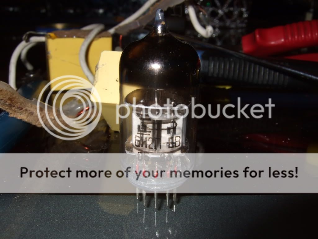
In meantime, Mikvous decided to have a go on Valve Itch Phono. I finally opted to use dead cheap, channel screened, low grid current, low self noise, long life Ruskie 6N2PEV (12AX7 like gain but different pin out) and 6SN7. We could do the prototype with my special rare Siemens E283CC, but I will use them personally later. I better give out to those of you hollow state hearted, HV experts something rather relatively cheap to do and feasible. I have to meet him and measure it, see the RIAA curve, make mods in it where is necessary. As it is now, right out from initial schematic based on 12AX7 cr@p models, he reports it dead silent, and zero microphonic with strong sonic grip. I am sure that right now it must be all over the place considering what I want to tune it to be. Will let you know. It has to beat the Bench or get the highway. Either its really good or it dies on the spot. If it proves itself as an occupant of an alternative but coherent sonic ground, standing the acid test of AB with the NJFET and Bench, after my inspections and schematic tunings, expect a vacuum state phono thread.
")
Re: OT sme3009 imp
Thank you nicoch46
I already had seen this mod.
Please report if you do it and what are the major benefits.
Ricardo
PS: The obligato caps are burning nicely and the sound is now open with good soundstage, very good detail and attack.
I like them.
Ricardo
nicoch46 said:HI Ricardo as I can have for gift a 3009 for add a second arm for dl103... we can put a bronze knife bearing for add mass and better sound..
bronze
Thank you nicoch46
I already had seen this mod.
Please report if you do it and what are the major benefits.
Ricardo
PS: The obligato caps are burning nicely and the sound is now open with good soundstage, very good detail and attack.
I like them.
Ricardo
your obbligato are gold premium?
what difference from premium ?
this are from homemadehifi (for speakers )
Obbligato aluminium-foil MKP 630VDC – 5% tolerance
Sound: Analogue is the word that keeps popping-up in my head when trying to describe these capacitors. They have a rich texture and produce and open and smooth image with realistic dynamics and good retrieval of ambient information. They have slightly less depth than a Clarity Cap DTAC but are also very detailed and never get harsh. They seem to have a sort of “detailed warmth” about them. Very nice especially when you look at their price!
Verdict: 10....
Hi nicoch46
The Obbligato Gold premium aluminum film caps (630VDC) differ from the premium just because they have a non magnetic case.
I have never seen another cap using such a case... it looks like a heavy 1mm gold tube with a cap inside.
I agree with the http://www.humblehomemadehifi.com/Cap.html comments.
Inittially they sounded a little "closed in" but now the bass is very present and the TT sounds like a TT again. Quite good for a budget cap.
I have a large very focused soundstage.... Just needs some edge detail to be outstanding.
I am now waiting for the Russian 100n Teflon to replace C1.
Did you ever hear a modded SME 3009 with bronze bearings ?
Ricardo
PS
The TT is killing the CDP
The Obbligato Gold premium aluminum film caps (630VDC) differ from the premium just because they have a non magnetic case.
I have never seen another cap using such a case... it looks like a heavy 1mm gold tube with a cap inside.
I agree with the http://www.humblehomemadehifi.com/Cap.html comments.
Inittially they sounded a little "closed in" but now the bass is very present and the TT sounds like a TT again.
Quite good for a budget cap.I have a large very focused soundstage.... Just needs some edge detail to be outstanding.
I am now waiting for the Russian 100n Teflon to replace C1.
Did you ever hear a modded SME 3009 with bronze bearings ?
Ricardo
PS
The TT is killing the CDP
RCruz said:
PS
The TT is killing the CDP
bad news for you
must buy LP !"Did you ever hear a modded SME 3009 with bronze bearings ?"
No Ricardo, dl103r +bronze mod are in range 300€....better do this summer ....at last I will tray to downgrade my rega p3 to grab the RB300
humm 3 tomearm ?

sme on dl160
rb300 dl103r
An externally hosted image should be here but it was not working when we last tested it.
an old nottingham audio spacedeck plus mentor arm
Hi guys, I hope you're not getting sick of my twists to the regulator. There is an improvement that I would like to report. salas, you've already seen the opamp version, and I have improved that too. The psrr plot of that (simulated) is superiour by a mile to any other regulator I have seen published on the net. I have implemented it too, but there is something about the sound which is off. I cannot trust my years, but I prefer your regulator which does not have an opamp.
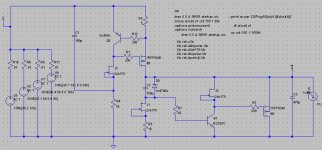
However, I have made a small change which has further improved the performance, both in simulation and in real life. I have built it tonight and the scope trace is as thin as the GND line (even a little thinner). The sound is good too.
Another detail which might help others: a ceramic 100nF capacitor right at the B+ and GND entrance to the njfet phono is a great improvement (high freq. filtering).
Here is the schematic.
Attachments
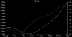
Yes, you wouldn't believe the psrr of the super opamp circuit. In simulation. I put a picture of the psrr in its thread in solid state.
Yes, the small change is the jfet loading of the bjt. Its psrr curve is close to the Jung regulator, without an opamp. Not bad.
Edit: I am not sure how to explain the sound of the opamp circuit. Somehow restricted, but somebody else should listen to it; it's easy enough to build.
Yes, the small change is the jfet loading of the bjt. Its psrr curve is close to the Jung regulator, without an opamp. Not bad.
Edit: I am not sure how to explain the sound of the opamp circuit. Somehow restricted, but somebody else should listen to it; it's easy enough to build.
This extra JFET CCS for the BJT we have checked out here too and we all got somewhat better sound, but Ricardo got the most subjective benefit. Maybe because he uses a cascode first stage. Its code name is ''R6 mod''.
For the 100nF directly on the B+ receiving end to gnd, I have to agree, the more the wire length from shunt to phono, the more work it does. I have recommended that to Ricardo and vgeorge. Always to be used when separate PSU and Phono boxes are employed. You can see it on mine too, where the red and black B+&GND twisted pair meets the phono board.
Here
Also some initial tests on our reg with R6 mod here. Given what you said about the super performance op amp reg's sound in practice, I guess that practically the phono gets a good DC service already, and we can not hope to find significantly better very easily or at least as simply?
salas said:
Till then I will see to post 5 schematics with standard part numbering and 3 different sensitivities, so you can rename the parts to follow. I will post 3 with cascoded input and 2 with non cascoded input. Also shunts with standard schematic but set for the according Vouts.
Salas- thanks. I'll wait on the corrections. Then we are all talking the same part #'s. I will try to design a matching shunt PCB (the R6 mod one) as well.
One thing I'd like to do is to make more room for bigger R's; namely the 2W Kiwame's you and others are using. What is the size of them? I do hate standing them on end- ugly!
-Kent
- Home
- Source & Line
- Analogue Source
- Simplistic NJFET RIAA