Installing the RIAA/Pre directly underneath the tone arm pedestal minimises the cable length............. Remember cabling brings a fair deal to this also when thinking about ultimate numbers.
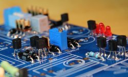
Anyway I ended up mounting the 2sk170BL's like this:
Q4 Idss: 8.33
Q5 Idss: 7.60
Q6 Idss: 8.80
For curiosity I tested them all in my little second stage dummy and performed automatic RMS measures with my Pico. It variated at the most between 5,021 and 5,040 VRMS since all was from same batch. Between the pairs it variated max 0,004 VRMS. Totally uninteresting for the performance of the riaa but interesting for other reasons maybe.
Attachments
A good amplifier design will have it's performance controlled by the fixed parameters of the feedback components.
It's performance will be relatively unaffected by the variations in semiconductor parameters.
Anywhere in the circuit where a source or emitter resistor is used is feedback.
These fixed parameter resistors are mostly responsible for amplifier performance.
Any in circuit test using internal feedback will swamp the transistor variations, when the correct semiconductor is used in each location.
A test jig to measure, or compare, jFETs or BJTs that has a resistor in the source or emitter is nearly useless for "seeing" differences in transistor parameters.
Look at post13335
There is a source resistor in that circuit.
That circuit will not reveal differences in transistor parameters as easily as a "no source resistor" test jig.
Last edited:
Finally got back to working on the phono stage.
Must admit again to my apostasy - using a Belleson 35 volts regulator instead of the on-board shunt.
Everything seems to work, but in the time since I first had a "working" board (in quotes because it never produced any sound - only tested it until something went wrong) I may have forgot how long it takes to reach the magical 3.6 V.
First off, to those who read this and have yet to apply power to your PCB - I now see (always have to learn the hard way) that when SALAS says to turn it on and leave it alone for 20 minutes, assuming one centered the pots before inserting them into the board, he is telling you something very important.
I immediately started fiddling with my one remaining pot and I am sure this is why it is taking so long to find the right spot.
BUT, is it normal for bias to take well over an hour to be reached? Just curious.
I made little lead hats for the 369's and this seems to speed up the process, I cannot imagine how long OR IF I would reach 3.6 V without them. They do not fit tightly around the 369s and there is a little space at the bottom so they are not sealed tight but I do think they add a measure of consistency. This is very early on and not meant as a proof of goodness, just a reporting of what I have done.
Mainly wondering if my slow attaining of correct bias is normal or is it signaling something else I have done wrong.
Voltage from the reg at the board is 35.05 volts. The reg has a bleed resistor at its output to waste about 20 mA. The raw supply is a pair of old DYNACO ST-150 power transformers (50-0-50), full wave with a pair of MBR735 that I had laying about into a HAMMOND 5 Hy/26R/500 ma choke, a 4700 uf cap and a bleed resistor whose value I cannot remember for an output when connected to the board of 40.5 volts. Glad to be putting these old lumps to work. No additional series resistance in the supply.
Of course, nothing beats connecting it up and hearing if it makes a sound. This should happen a little later on today.
The higher the internal temperatures the longer it takes for temperatures to reach final.
During that time bias of many parts will change.
Keeping everything inside cooler shortens temperature stabilisation time.
My experience, now with the second board, is that if left out in the open air I do not think it would ever reach 3.6 V.
I do think the lead hat idea was bad. Had to try it. If that is what you were speaking to directly you are unequivocally correct!
I have now built a small enclosure around the PCB (sits upon the PCB) with thick wool felt and using a piece of SCOTCHBRITE pad as the top. This allow, I think, a fairly constant temperature. The SCOtCHBRITE seems to breath just the right amount.
I have got a fairly steady 3.6 - though one wonders what will happen in the winter? Not that it would bother me to have to check on it when the room temperature changes.
No question, this is a phono amp that should be left on which is what I would have done anyway.
Now to listen to it.
Should we start a thread dedicated to the Folded Simplistic boards, for building & listening impressions, etc.?
There is a Group Buy thread, and this, but it's not specific.
A lot of FSP board builds have been featured here already. It will leave a mess behind if to move them in a dedicated thread.
Salas,
OK, fair enough about keeping this thread the central place. I haven't heard much in the way of listening impressions though. They always help to generate enthusiasm and popularity of a circuit.
Tea-Bag,
I now realise from the notes that for an MM phono circuit, I didn't need to buy a quad of 369BL fets.
Are quads rare and very in demand? Shall I return them for a pair, or just use a pair and sell the other pair? No problem either way for me.
Keep it for future modification to MC. You may have an MC cart someday, but 369s won't be around anymore. Especially matched 369s.
Very good advice
")
My transformer with dual 30V secondaries arrived today and I am happy to say that my MM FSP is now totally hum free
I have 46.5vdc going into the FSP boards and was able to set TP1/2 voltage to 3.6ish which remained stable over 60mins or so.Rail to ground was 34.2vdc on one channel and 33.7vdc on the other.
Lucas I don't think you will be disappointed in the performance of this little beauty.
Gonna have a proper listen tomorrow.
Thanks again Salas
Last edited:
- Home
- Source & Line
- Analogue Source
- Simplistic NJFET RIAA