A DMM hFE test is done at a tiny base current.
That base current depends on the Vbe of the DUT.
The result is that the hFE is useful for batching nearly equal DUTs, ready for proper testing under controlled conditions with a KNOWN Ic.
That last part is very important.
ESPECIALLY if you are matching transistors for BOTH hFE and Vbe.
If small errors in Vbe don't matter and small errors in hFE don't matter then testing at an UNKOWN IC may be good enough.
They are all in the BL range.
Chances are good.
BUT complete the checks.
sk170 have a LOW Pinch Off Voltage.
That pinch off is directly related to the measured Idss.
measure both and compare.
Ok thanks. How do I measure that?
Batteries are about 27.5V unloaded. They are a little used so I expect about 30V loaded with fresh batteries.
I've got 3.6V across R4. I have a trimmer I can adjust if needed.
Thanks Salas.
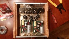
Salas phono is complete. Battery powered for now, 20 AA batteries. Still making some adjustments and tweaks but for the short time I have used it...it is really, really good. A step up from the le pacific style riaa stage I was using.
Thank you Salas. You are a genius.
Attachments
Last edited:
Ok thanks. How do I measure that?
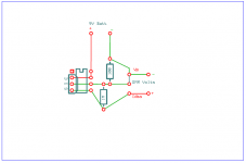
I use this circuit and it works wonderfully:
Attachments
Salas phono is complete. Battery powered for now, 20 AA batteries. Still making some adjustments and tweaks but for the short time I have used it...it is really, really good. A step up from the le pacific style riaa stage I was using.
Thank you Salas. You are a genius.
Wait till you connect it to Salas shunt... then you will really freeze
")

Wait till you connect it to Salas shunt... then you will really freeze
I need 30V-ish out and I don't have a suitable transformer or case right now. Attached is the schematic from the original simplistic phono build guide.Should I use this or has it been superseded by something better?
Attachments
I use this circuit and it works wonderfully:
So the 3 dots next to DMM is a switch that either shorts Gate and Source and puts a 100R in series OR shorts Drain and Gate and puts a 1M in parallel (as in pic)?
What is the expected result to compare?
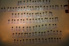
Here is my new batch of suspected K170BL's. Predominantly 9ers and 10ers as can be seen which is not really strange in a production line that aims for 6-12 mA.
Here I have two 8,33 (some reflexes there) for example for Q4 usage maybe. Also two in 8,48 if that would be to prefer.
As for Q5 and Q6 there is lots of options.
Q5: 7,58/7,61 maybe to not steal from eventual future Q4 needs?
Q6: Lots of options from 8,5 and up.
Lower row is Mikes batch. They look very similar in body, legs and print. New batch says 3F in the end, Mikes 9D. Slight colour difference on print to, Mikes whiter.
What would you guys go for?
Attachments
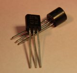
Mainly by VGS (off) and IDSS follows datasheet. Their construction details look Toshiba to me though.
Authenticity real test is by full curve and parameters test against datasheet and some sure original samples. Including noise.
Simple method for NJFET VGS (off) with just a 9V battery and DMM (DCV mode) is
BAT (+) D pin.
BAT (-) G pin and DMM black.
DMM red to S pin.
(DMM has to have 10 Meg self resistance or there about, don't use LowZ mode).
Thanks,
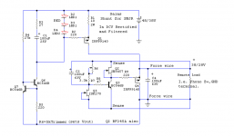
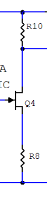
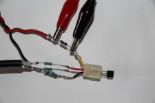
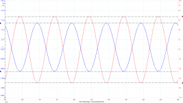
First, mostly out of curiosity, I rigged the second stage for measuring purpouses. There is a 6K8 on Drain and a 47R on Source. I also putted a 180R on Gate for some reason.
The 180R on gate is directly soldered on a 50 ohm coax with a BNC in the end sitting on the 102 dB function generator of my PicoScope 4262 sending in a 100 mV sine. Its screen goes to the bottom of the 47R.
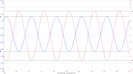
6K8 on top got 35 VDC from a twisted pair with its return back to the PSU. and first I tested one of my new 2SK170s with Idss 7,34. Out came an inverted signal of 14,1 V P-P.
Then I tested one Idss 7,33 from Mikes and got 13,7 V P-P out.
Sine In in both cases measures 199,3 mV P-P.
Voltage over 6K8 was 34,6 V on the 7,34 one and 34,59 on Mikes 7,33.
150 mHz probes on x1 on both channels.
Can this be normal? Does it say anything of interest?
Pics are Setup, new k170, Mikes k170.
First, mostly out of curiosity, I rigged the second stage for measuring purpouses. There is a 6K8 on Drain and a 47R on Source. I also putted a 180R on Gate for some reason.
The 180R on gate is directly soldered on a 50 ohm coax with a BNC in the end sitting on the 102 dB function generator of my PicoScope 4262 sending in a 100 mV sine. Its screen goes to the bottom of the 47R.
6K8 on top got 35 VDC from a twisted pair with its return back to the PSU. and first I tested one of my new 2SK170s with Idss 7,34. Out came an inverted signal of 14,1 V P-P.
Then I tested one Idss 7,33 from Mikes and got 13,7 V P-P out.
Sine In in both cases measures 199,3 mV P-P.
Voltage over 6K8 was 34,6 V on the 7,34 one and 34,59 on Mikes 7,33.
150 mHz probes on x1 on both channels.
Can this be normal? Does it say anything of interest?
Pics are Setup, new k170, Mikes k170.
Attachments
Last edited:
It says differences in transconductance (Yfs). It also says that batch has expected Yfs levels. Even two same Idss fets can have small vgs dif that translates to bit different gain factor. Care more about voltage amplification matching in a no loop feedback (= no auto gain control) preamp like this.
It says differences in transconductance (Yfs). It also says that batch has expected Yfs levels. Even two same Idss fets can have small vgs dif that translates to bit different gain factor. Care more about voltage amplification matching in a no loop feedback (= no auto gain control) preamp like this.
So I can use this as complementary matching to Idss?
- Home
- Source & Line
- Analogue Source
- Simplistic NJFET RIAA