My results fit with Nezbleu experience.
Ideal rail voltage is usually what gets the TP1-2 in range. Mine was lower than expected as well. Proto was 31-32v and Current LOMC is 33v I think.
If it all lights up without smoke or excessive heat, let it bake for a bit and see what results you get.
Ideal rail voltage is usually what gets the TP1-2 in range. Mine was lower than expected as well. Proto was 31-32v and Current LOMC is 33v I think.
If it all lights up without smoke or excessive heat, let it bake for a bit and see what results you get.
And I have made no progress.
Replaced Q3 - made no change with TP1/TP2 or anything else.
Measured the current across Rs 1&2 - comes out to just under 9mV - using 4R resistors.
...
Any suggestions?
Thanks and take care,
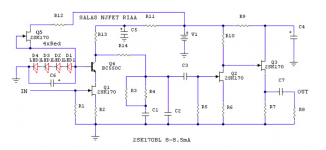
9mV there across 4 Ohm means 2.25mA current through each 369. Problem. It needs reach 9-10mA. Make sure R13 is 1K2 indeed. If R13 is correct value then you need troubleshoot further. You could have a problem with the main CCS in the reg not providing enough current if you actually had created a problem when you accidentally tweaked there or the 369s could be shot.
Moves:
Check that the Q1x IRF9610s work. Are their sinks getting hot (that is a good thing), do they develop 3-4V between G&S pins? What is the voltage across each R1x and is it 15R indeed?
What are the DCV to ground readings at: Q1, Q4, Q6 drain pins?
Are photos of each board channel possible, maybe we can spot something?
Are R2 & R3 4 Ohm indeed?
If you remove a 369 and remeasure its IDSS, is it healthy and as expected?
(I have concealed the power LED from my wife so I can leave it on all the time.)
My results fit with Nezbleu experience.
Ideal rail voltage is usually what gets the TP1-2 in range. Mine was lower than expected as well. Proto was 31-32v and Current LOMC is 33v I think.
If it all lights up without smoke or excessive heat, let it bake for a bit and see what results you get.
I am abusing my prototype a little for bias current in the input FETs bcs I had a bit lower R2 R3 values than optimum at the time of tests and high ambient temp (August in Greece) so I got above 33V maybe 34.2 if I remember correctly, but its no problem if different IDSS 369s different ambient and different R2 R3 values make somebody arrive at 31-32V for instance. There is VR1 that can restrict the current available through R13 a bit leading to higher Rail+ but I would engage VR1 mainly when there are IDSS tolerances between channels that force more than 1V Rail+ dif settings between them.
Hi Salas: This reminds me of something. My cartridge is rated as "0.25mV", although one always wonders exactly what that means. Does it mean @1KHz @ 3.54cm/sec? Or @5cm/sec? Or "0.25mV/cm/sec"? Anyway, I feel my LOMC folded has plenty of gain even into my DCB1. In fact I could live happily with a little less gain, say 6dB less would probably let me keep the volume control about the same for phono and other sources. If I wanted to decrease the gain a bit, I assume slightly higher R2 and R3 would increase degeneration and lower the front-end gain, while also slightly lowering thermal effects. Your excellent PDF doc makes it clear that there are other considerations when selecting gain config, particularly R13.
I`m probably not going to pursue this, but if I wanted to reduce the phono stage gain just a bit, what would be the best approach?
I`m probably not going to pursue this, but if I wanted to reduce the phono stage gain just a bit, what would be the best approach?
Many Japanese manufacturers usually refer to a JVC test record that appears in such a way modulated so when their carts are measured on American standard test records they prove 1.414 times stronger than claimed. That historical standard JVC record does not state the velocity in RMS or PEAK so there started some confusion. It appears to be 3.54cm/sec PEAK so 3dB less than 5cm/sec 1kHz which gives 3.54cm/sec RMS in the 45deg lateral for stereo. That 3.54cm/sec RMS lateral stereo is what we assume as 0dB record modulation. Can reach +20dB max modulation. You have seen some +18dB torture tracks in test records for instance. They don't go up there for music because of tracking error THD increase with higher modulation unless surface anomalies do that (clicks and pops). But +6dB peaks in music records aren't that seldom or even more in especially dynamic cuts.
As for your own optimum gain tweak values query just remind me your 369s IDSS and I will study an overall balanced suggestion to reply.
As for your own optimum gain tweak values query just remind me your 369s IDSS and I will study an overall balanced suggestion to reply.
Thanks to all for your time and trouble.
As usual I screw up between mV and mA in my post.
I measured SLIGHTLY under 9mA not mV. My apologies for this.
I meant to also say that when I replaced the "970" at Q3 with BC560 I get the same .7 V across as I got with "970". Yes, this is respecting the different pin out.
I am leaving the board on until I get fully heated heatsinks. Nothing changes much from cold to heated.
The other thing to remember is that with this board I was able to get the proper bias voltage until I placed a resistor in series with R6x instead of R3x in an attempt to raise the voltage at rail/ground. A very stupid mistake.
I will make the suggested measurements.
I tend to think there is something in the regulator. I surmise it is not generating the current needed. All I can do is surmise. I do not know enough to do much else! Which is why I asked if the regulator could be ignored here or is still in the running for the problem area.
The 369s were of the recommended value and matched. I did not write down any of this stuff and that is a lesson learned. Next time I will document. Rs 1&2 are 4 ohms.
NEZBLEU, I too, have found with my working board that the temperature sensitivity is quite extraordinary and getting to the correct bias is something that takes a long time. My working board instructs me what to look for in that respect. The BAD board has no temperature sensitivity at all in comparison.
I am no longer obsessing over the rail voltage! With the working board, I too, have ignored rail voltage. My only concern is with TP1/TP2. With the working board my rail/gnd is just under 35 volts and there it shall stay. Compliments to Mike on this one!
Thanks very much for you comments and encouragement.
Now to go make those measurements SALAS suggested.
Thanks to all and take care,
As for your own optimum gain tweak values query just remind me your 369s IDSS and I will study an overall balanced suggestion to reply.
All 4 369's were 11.55mA Idss. I didn't measure them, they were sold as a matched quad.
All 4 369's were 11.55mA Idss. I didn't measure them, they were sold as a matched quad.
I believe your cart is 0.35mV-0.42mV depending on load in reality and you could use 59-60dB of gain. I will let you know.
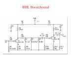
I am currently using a BHL/Boozehound Jfet pre based on the "La Pacific" preamp which is really kind of a similar design to the Salas Nfet, although not as refined.
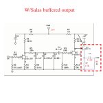
I've been longingly eyeing the Salas NFET schematic...I am thinking about incorporating the output buffer into my Boozhound preamp. Schematic attached.
Would this work? Good idea or bad idea? Is this worthwhile even without all the first stage improvement Salas has developed in his pre?
I've been longingly eyeing the Salas NFET schematic...I am thinking about incorporating the output buffer into my Boozhound preamp. Schematic attached.
Would this work? Good idea or bad idea? Is this worthwhile even without all the first stage improvement Salas has developed in his pre?
Attachments
Thanks to all for your time and trouble.
As usual I screw up between mV and mA in my post.
I measured SLIGHTLY under 9mA not mV. My apologies for this.
I meant to also say that when I replaced the "970" at Q3 with BC560 I get the same .7 V across as I got with "970". Yes, this is respecting the different pin out.
I am leaving the board on until I get fully heated heatsinks. Nothing changes much from cold to heated.
The other thing to remember is that with this board I was able to get the proper bias voltage until I placed a resistor in series with R6x instead of R3x in an attempt to raise the voltage at rail/ground. A very stupid mistake.
I will make the suggested measurements.
I tend to think there is something in the regulator. I surmise it is not generating the current needed. All I can do is surmise. I do not know enough to do much else! Which is why I asked if the regulator could be ignored here or is still in the running for the problem area.
The 369s were of the recommended value and matched. I did not write down any of this stuff and that is a lesson learned. Next time I will document. Rs 1&2 are 4 ohms.
NEZBLEU, I too, have found with my working board that the temperature sensitivity is quite extraordinary and getting to the correct bias is something that takes a long time. My working board instructs me what to look for in that respect. The BAD board has no temperature sensitivity at all in comparison.
I am no longer obsessing over the rail voltage! With the working board, I too, have ignored rail voltage. My only concern is with TP1/TP2. With the working board my rail/gnd is just under 35 volts and there it shall stay. Compliments to Mike on this one!
Thanks very much for you comments and encouragement.
Now to go make those measurements SALAS suggested.
Thanks to all and take care,
Lets make sure VR1 isn't shorted also. When power is off what Ohmic value can you measure for R12 and is it the same between the working and problematic channel?
Shoot a photo of the problematic channel board too if possible, it may help us see some detail done unusually if there is any.
I am currently using a BHL/Boozehound Jfet pre based on the "La Pacific" preamp which is really kind of a similar design to the Salas Nfet, although not as refined.
I've been longingly eyeing the Salas NFET schematic...I am thinking about incorporating the output buffer into my Boozhound preamp. Schematic attached.
Would this work? Good idea or bad idea? Is this worthwhile even without all the first stage improvement Salas has developed in his pre?
That last schema is not FSP arrangement but previous with telescopic cascode. Alexkosha had one like yours or similar but he had invested further with upgraded components and SSLV1.1 BIB regs and filters alright. Then he made the FSP (folded simplistic) on its dedicated board so he is the best experienced man to tell you if it is worthwhile upgrading bits in general and how close you can reach.
Meanwhile to incorporate that source follower right technically you should test for an R7 value that with the voltage drop across itself it does not compute more mA than your Q3 IDSS.
Disclaimer is that I am not the Boozhound author, I don't know if tweaks are even encouraged, and you better ask his opinion and guide directly. He is a member of DIYA also.
More like a soap opera ...
Well, I measured the voltage across Q1x and Q6x - Q1x right around 4 Q6x around 3.5.
When I make these measurement I have the power off while I attach the leads and then I turn it back on.
After making those measurements, power off, remove leads, turn the power back on and now the LED quartet is dim and Rail/Gnd measures around 7 volts. Turning VR2x makes no difference.
Could a trimmer really go bad? Not as if I have been using it that much! I will check it as per your instructions.
No need to make any more measurements on that board!
WELL, I thought, I will try to restore some credibility to my assembling ability and see what the working channel sounds like. After all, it seemed to be behaving as expected. Well, it makes no sounds at all.
So, my credibility has ceased to exist.
I expected this project to be a challenge and that is one reason why I wanted to do it. Now I am starting to wonder if I should stick with tubes! Not looking for sympathy or encouragement - just as honest assessment.
I had connected my cartridge input to the holes on either side of R1 - using the TX2575 as R1 leaves the other holes free. Not using the switch at all. I assume I do not need to do anything else here. At the output I am using Slagle Autoformer attenuators. I cannot imagine they are the problem but I will try bypassing them tonight. Checked ten times that in and out are wired correctly.
Oh, well, I am disappointed. Not depressed or ready to give up. I will take photos but I do not think you will see anything unusual. Of course, I no longer can assume either board ever worked correctly .
I wonder if I should start all over again?
Its an easy project, all managed it to work by now with very few bad incidents, almost zero. Take a break, let the community help out.
Who that is located in USA or Canada and feels confident having made an FSP already can help Rick if he could send his boards out for inspection and minor possible repair?
Who that is located in USA or Canada and feels confident having made an FSP already can help Rick if he could send his boards out for inspection and minor possible repair?
Rick. Its just feelings after long hours of desperate fixes. We have all been there. Have yourself a good bunch of Guinness at the nearest bar and let some steam out. We will help you make the investigations in proper order and solve it together when your ready. Promise.
Thanks for the kind words
I want this to work and with time it will work.
I want this phono amp!
I figure the problem is in more than one of the FETs but I am not much for taking them out one by one.
Mike Thomas has offered to sell me new FETs so I am going to remove all semiconductors. Then I can verify the caps and resistors are what they are supposed to be. I used many TX2575s which I assume to be what they said they were but what if they are not? I did not verify any of this stuff just as I did not keep track of the IDSS values of the FETs I used. I DID make sure to use a similar value in each channels "position". I used CADDOCKS and a few tantalums, same goes for them!
Figure there is nothing to fear with the caps!
On reflection, I was careful, but in hindsight a somewhat careless form of careful. No notes were taken and for all to see based on my mistakes one who must have assumed he was doing something right when he wasn't. I have always said education is expensive but it is much better than ignorance!
So tonight, between sips of rye whiskey (I like GUINNESS but I am a whiskey drinker - and no, that is not the problem, I hope it is not the problem!) I will start removal of the FETs and hope I am careful enough that I do not destroy them (if they are not already destroyed!) and can be tested to find out what went wrong.
Give me a couple of weeks and I hope to join the ranks of those who are enjoying SALAS's fine gift due to the efforts of Mike Thomas to make it easy for us and especially for me. Mike is, beyond words I can come up with, a very fine fellow.
Last edited:
between sips of rye whiskey
I have had this tinker prob for a while. I was about to build in 4 noice protection transformers behind my tinker desk. Two was for the measuring equpment, scope comp divided. Two was for voltage sources. Tho two of them started to fuzz and get warm so I disqualified them. Now one more starts to get bangy after mounting.
The reason for mounting all of them was to being able to do some reliable measurements b4 I start building riaas.
Now I think that I throw them all on fire and buy some new ones. But then again. I am again a tinkering guy. I have to find out why they perform like this. So I have no working bench. Thats how it is. To be a tinker guy.
- Home
- Source & Line
- Analogue Source
- Simplistic NJFET RIAA