Last post for tonight: next step is to mount my Ortofon MC in my turntable to give this thing a listen!
Once again, and as always, Salas, thanks so much for such a great design and such a fun project, and to TeaBag for making it so easy.
It is good isn't it
")
Regards
Ok, there we have it - thanks for the explanation salas - I didn't think about looking for the answer on the pcb...
So the main chassis is at signal ground. Any sonical effects if you touch it?
Regards
It would have hum, EMI, RFI, effects if it was not grounded at signal level ground potential. As it is, when boxed, I had difficulty making it sing along most mobile phones transmitting. Only a little if ever.
Ok, there we have it - thanks for the explanation salas - I didn't think about looking for the answer on the pcb...
So the main chassis is at signal ground. Any sonical effects if you touch it?
Regards
I will reply to myself and elaborate more on the issue. PE the main chassis though the umbilical which you in the raw psu have connected to the chassis and PE. In the main chassis use an isolated ground terminal connected to the pcb's GND which provides signal ground for the TT.
This would give both safety and function
Regards
You got a box that contains mains and one that does not. Contains sensitive amplification. Its better to associate one directly with the mains ground and the other with the signal ground. They ultimately refer to each other through the disconnection network.
Hi Alex.
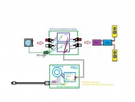
As is the umbilicals shield is connected to 0 (signal gnd) and not protective earth.
That is the yellow line in the drawing. So the main box should be yellow.
If PE'ing the main chassis spoils SQ then I rather keep it as is. Better would then be to have double chassis with PE on the outer chassis or external isolation.
Regards
As is the umbilicals shield is connected to 0 (signal gnd) and not protective earth.
That is the yellow line in the drawing. So the main box should be yellow.
If PE'ing
the main chassis spoils SQ then I rather keep it as is. Better would then be to have double chassis with PE on the outer chassis or external isolation.Regards
Hi Alex.
As is the umbilicals shield is connected to 0 (signal gnd) and not protective earth.
That is the yellow line in the drawing. So the main box should be yellow.
If PE'ing
Regards
Hi Turbon,
Salas wrote us that umbilical cord shield should be connected at PSU side only to the GND. Do you meant that we need to connect it to FSP TT lug which is a part of FSP chassis and not at PSU side?
Hi Alex.
No, the umbilicals shield is connected to 0 (signal gnd) on the raw PSU side only - not to the FSP. The FSP takes the 0 (signal gnd) from the GND on the pcb's and connects it to the FSP chassis/TT ground lug.
Again: "If PE'ing
 the main chassis spoils SQ then I rather keep it as is. Better would then be to have double chassis with PE on the outer chassis or external isolation."
But thats me and I would be happy if there is an easy way to PE the FSP without me needing to rebuild it. For now I enjoy it as is per salas design
Regards
No, the umbilicals shield is connected to 0 (signal gnd) on the raw PSU side only - not to the FSP. The FSP takes the 0 (signal gnd) from the GND on the pcb's and connects it to the FSP chassis/TT ground lug.
Again: "If PE'ing
But thats me
and I would be happy if there is an easy way to PE the FSP without me needing to rebuild it. For now I enjoy it as is per salas design Regards
Last edited:
Hi Alex.
No, the umbilicals shield is connected to 0 (signal gnd) on the raw PSU side only - not to the FSP. The FSP takes the 0 (signal gnd) from the GND on the pcb's and connects it to the FSP chassis/TT ground lug.
Again: "If PE'ingthe main chassis spoils SQ then I rather keep it as is. Better would then be to have double chassis with PE on the outer chassis or external isolation."
But thats me
Regards
Got it. I attached corrected drawing.
Attachments

Got it. I attached corrected drawing.
Yes Alex. That is as I understand it described in the build PDF and clarifications from salas earlier in the thread.
Regards
Yes Alex. That is as I understand it described in the build PDF and clarifications from salas earlier in the thread.
Regards
Thank you.
Just to be clear, the GND in the PSU is not the same as GND in the FSP...
Regards
If 0V of Raw PSU is connected to FSP, then FSP as Raw PSU are separated from Earth Ground by 1R and 10R ll with 2 diodes.
If 0V of Raw PSU is connected to FSP, then FSP as Raw PSU are separated from Earth Ground by 1R and 10R ll with 2 diodes.
Yes, that was even clearer
Regards
The Builder MUST decide if they require the Fault Current Route to extend all the way through the system.
Once that decision is made, you either
a.) connect the various chassis together any which way that achieves the "no Hum" condition.
or
b.) Ensure that every connection in the Fault Current Route can survive the kilo Amperes that can flow until after the Mains Fuse has ruptured and the arc extinguished.
The recent discussion seems to be going along the a.) option.
But that is up to each individual Builder and his Family and his/her Visitors and the household insurance company.
Last edited:
I assembled the raw dc supply using the GB pcb and an Antek 3212 transformer and all is well. I checked them with 470r load resistors and the raw output is ~45vdc on each.
The approach I am using for the next step is to populate only the shunt reg circuits, test them, then populate and test the gain portions as a separate step. For testing the shunts by themselves, do I need to load them to ~75ma (35vdc/470r) or can they just be run unloaded?
The approach I am using for the next step is to populate only the shunt reg circuits, test them, then populate and test the gain portions as a separate step. For testing the shunts by themselves, do I need to load them to ~75ma (35vdc/470r) or can they just be run unloaded?
Yes, I transposed it. AS-1232 is the one. 2 x 32vac non-ct windings. Line voltage is typically fairly high here.Better load them bcs the output sink is rather small to be tested totally unloaded in prolonged time. The MOSFET will hold, but better not allow somehow cook it.
P.S. AS-1232 maybe?
- Home
- Source & Line
- Analogue Source
- Simplistic NJFET RIAA