Anyway it is good to know we can fiddle quite a bit with Vin without compromising performance")
The TP1-TP2 target voltage delta in the PCB always produces Q3e node 1/2 at TP2 VS GND. Since we know our D1-D4 voltage will be 7.75V. This TP1 its like your TP1 minus Vbe. Less to know, less to do. Automatic for the people.
Hello,
in the Paradise preregolator every rail is separated so I think is very easy to configure for about 50V out.
Is the 9610 regulated for about 150mA?
I'm thinking to configure the output of the preregulator directely on an industrial multipolar connector, with this solution I'd like to use it for many circuits.
Ciao
Guglielmo
Are you going to use the original phono board? If not and the regs will be separate and away enough on an off box sink then you can hot rod them to 300mA. Although the integrated regs co-work excellently. The bass is solid and the highs clean. With 36VAC Tx and 10mA bleeders the main PSU is going about 46VDC. You gonna need the bleeders for it to drain out acceptably fast when you power down.
Not at this position for the signal level and THD fed, pretty transparent. A tube buffer has 100% feedback too, maybe VS common cathode triode it can be less life like.
Interesting! So you mean that if the input signal swing is small, than the result is good. What about THD? Is there some sort of distortion cancellation between the two stages?
Ciao
Sweet spot cancellation can be homed in if having good resolution FFT rig by using 100R trimmer as rheostat around the 45-55R mark for R8. After best THD profile and/or channels matching is achieved it should be removed & measured for value. Then replaced with closest value low ppm low noise fixed resistor. Due to Q4 subtle differences and overall tolerances every build and every channel will have its own best value. Its a procedure that lab testing experienced builders can afford and implement right. Over 100dB dynamic range FFT and and very clean 1kHz sinewave at intended cartridge nominal level are required. Standard 47R R8 and semiconductors matching practice as in the guide give satisfactory builds nonetheless.
Less to know, less to do. Automatic for the people.
happened to me this one yesterday, found during tweaking the reg Q102 (BiB) SSLV1.1 runs hot to touch, idss ~7mA I'm using BC550B here, is this normal Salas? no influence on sound though, re-checked the board everything is right
Q102 is the LEDS JFET source. Q104 is the error amp BJT. Its dissipation depends on Q105 IDSS which biases it and the Vout level.
2SK117GR designated in SSLV1.1 is classified as 2.6mA-6.5mA by Toshiba though. BIB guide says use 3-5mA.
Its only a matter of long term reliability. Its either the Q104 will endure given moderate ambient temp or you change Q105 for less IDSS.
At a lower Vout application the dissipation will fall of course even as it is made now.
Salas
I will use Salas Folded Phono with MM cartrage
can I use sk170 Instead of sk369 for Q1
why did you chose sk369 over sk170
More gain on less noise for same degeneration. Its 1/F region is noticeably better too due to intrinsically superior GR noise behavior in the mid-bass and bass.
You can use K170BL if its absolutely necessary but I am sure Tea will be able to secure you just a pair of 369BL around the 11-12 IDSS mark which need not be terribly closely matched due to the large degeneration in HMC or MM advised settings equalizes them better. So you avoid to compromise.
In case you insist on K170BL which is no slouch for MM after all, you let me know your IDSS pair and I advise your special resistors values for that since there are Ygfs (current gain) differences between those types. If just dropped in for IDSS compatibility only it will bias the same but you will lack enough gain VS the correct target.
I confirm. Q2 & R3 are not used for MM. As clearly described in the PDF guide.
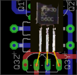
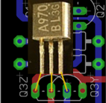
Any Japanese PNP with good Early voltage and low Cob in 1. Emitter 2. Collector 3. Base pin format fits the Q3Z position. See its >350 HFE too.
Else, any brand name high HFE BC560C in Q3Y position is sufficiently good.
Any Japanese PNP with good Early voltage and low Cob in 1. Emitter 2. Collector 3. Base pin format fits the Q3Z position. See its >350 HFE too.
Else, any brand name high HFE BC560C in Q3Y position is sufficiently good.
To clear any possible misconception, as already stated in the guide, you must use the recommended European type OR Japanese type PNP. NOT both.
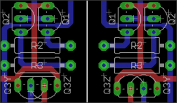
Here is how they visually go to PCB. In one channel you face their backs in the other their fronts in mutually shifted manner due to mirrored layout.
Here is how they visually go to PCB. In one channel you face their backs in the other their fronts in mutually shifted manner due to mirrored layout.
Attachments
I need you exceptional knowledge and vast experience
Dear Salas,
I need you exceptional knowledge and vast experience.
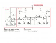
I recently found that Forum and surprisingly figured out that KIT which I purchased from BLH laboratory is actually based on your design. Please see attached schematics.
Can you please advice me how I should optimize it for my cartridge. I use Ply cartridge (actually made by Benz Micro for Wilson Benesch TT) which has Low 0.58 High 1.58 mV output. Resistive Load is 10-47k.
So far, I have some harsh in my mid-highs.
I also would appreciate if you will advice about PSU. I saw your shunt here, but it is so many variations of it that I confused.
If I deviated from the main course of that forum, I can give you my email.
Thank you in advance.
Dear Salas,
I need you exceptional knowledge and vast experience.
I recently found that Forum and surprisingly figured out that KIT which I purchased from BLH laboratory is actually based on your design. Please see attached schematics.
Can you please advice me how I should optimize it for my cartridge. I use Ply cartridge (actually made by Benz Micro for Wilson Benesch TT) which has Low 0.58 High 1.58 mV output. Resistive Load is 10-47k.
So far, I have some harsh in my mid-highs.
I also would appreciate if you will advice about PSU. I saw your shunt here, but it is so many variations of it that I confused.
If I deviated from the main course of that forum, I can give you my email.
Thank you in advance.
Attachments
Hi
The circuit you posted looks more like MadsK take on the Pacific than anything else.
The Folded Simplistic has its own shunt regs and bears no meaningful resemblance to that one except generalities.
You can get SSLV1.1 regs PCB from the GB that's on now if you want to try shunts.
The harshness could be due to the heavier than proper interstage loading and extra noise from the gate and source resistors values. IMHO of course. Circuit's internal workings in other words.
You could be over driving it also through the MC stage if you got the 1.58mV cart. Try the straight MM input in that case.
great tip! Thanks!Sweet spot cancellation can be homed in if having good resolution FFT rig by using 100R trimmer as rheostat around the 45-55R mark for R8........
Theoretically, where this best point should be? I mean, at a given supply voltage and collector load resistor, should Rs be as small as possible in order to work near Idss?
The point is where load line cancellation between drain current and drain voltage occurs where temperature plays a role too.
Since its not allowed to vary the drain voltage in this finished circuit (it would affect the other stages too) you vary the degeneration. And its usually ending up high enough Rs.
Keep in mind that when cancelling square law devices like tubes and fets the cubic product remains which is the third harmonic. You might want that or not, or to a balance.
Yesterday I received a batch of k369 and so decided to experiment with those (as you know I had only used k363 before and these mysteriously disappeared from the market).
I found that the dispersion is much wider than with k170, so with a 50 pcs batch I could only get 4 matched at 10.9mA
Anyway, I replaced the k170 for the k369 in one of my builds and am now very pleased with the results.... tighter bass, very good instrument integration and most of all lower noise floor.... much lower than with the k170.
The only change was the jfets and it´s drain resistor that came down from 1k5 to 1k2 as per last salas pdf.
k170 where 7.5mA and now I have ~11ma
Measured 9mA idling with 3.9ohm Rs.
Slightly higher gain with a VERY noticeable lower noise floor.
This might be what I need for my latest Benz LP experiments.
- Home
- Source & Line
- Analogue Source
- Simplistic NJFET RIAA