Re: pcb layout revisited...
Hi Kent,
It looks nice to me but I know next to nothing about PCBs. I like it aesthetically
I only guess that the signal ground and PSU ground will have to meet at an external star point with thick wires, so to reference to each other?
You did well to use coax. When it will go in to a box, and the cables will be short etc, your grounds neat etc, you can get 60Hz TT hum down to very low. At least my p2p or Michael's, or the 3rd one for his mate Chris measure -90dB (0dB=1V) hum on the FFT (50Hz in Europe) and -110dB 100Hz, level with the noise floor, i.e. no ripple with the shunt. Did you notice any 100Hz buzz yourself? Because Ikoflexer has strong ripple on shunt's out for some reason and we must find the bug.
kstlfido said:Here is my revised RIAA board layout... Look any good?
Listening update- still making little tweaks. Playing with load resistors and made some cables out of mil-spec silver plate coax (which did help hum a fair bit).
I accidentally put in some RLoads of 82k (thought they were 8.2k). Better- fleshed out the mid-bass and smoother highs. Less 'shouty' ?!?
-Kent
Hi Kent,
It looks nice to me but I know next to nothing about PCBs. I like it aesthetically
I only guess that the signal ground and PSU ground will have to meet at an external star point with thick wires, so to reference to each other?
You did well to use coax. When it will go in to a box, and the cables will be short etc, your grounds neat etc, you can get 60Hz TT hum down to very low. At least my p2p or Michael's, or the 3rd one for his mate Chris measure -90dB (0dB=1V) hum on the FFT (50Hz in Europe) and -110dB 100Hz, level with the noise floor, i.e. no ripple with the shunt. Did you notice any 100Hz buzz yourself? Because Ikoflexer has strong ripple on shunt's out for some reason and we must find the bug.
Re: pcb layout revisited...
Looks like your cart enjoys the lightest of loads and its generator pumps out easier in the lows? Off course such a high Rload equals more hiss, so I hope that with your final parts choices you will have the ability to voice it with a much lower Rload.
kstlfido said:I accidentally put in some RLoads of 82k (thought they were 8.2k). Better- fleshed out the mid-bass and smoother highs. Less 'shouty' ?!?
-Kent
Looks like your cart enjoys the lightest of loads and its generator pumps out easier in the lows? Off course such a high Rload equals more hiss, so I hope that with your final parts choices you will have the ability to voice it with a much lower Rload.
RCruz said:How do I measure VGS of Q1 ?
Ricardo
By touching the Voltage meter's probes on its left and right pins (red probe on right pin) when there is power on.
Kent, this is a very nice looking layout. There has been some discussion about the 2sk170 based CCS, and it seems that G and S are tied together, while D is separate and connected to the more positive voltage. That would change a bit the ping lettering on J1 on your board.
Those with MM carts, an empty spot for the loading input cap could be added easy enough.
If you're willing to share, is it possible to post the top and bottom layers separately? I don't know how one can print them separately from your image, for etching.
Thanks for all the work, if I was doing another board I'd certainly use your layout.
Hi Salas
Maybe it survived because R1 took it like a man (Touching the sinks, the shortest way between GND and +Vin looks like R1)
By the way, R1 is 14r so I believe I = 164mA. (Might reach 204mA without output load)
I am glad because these where the values I calculated before implementation
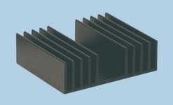
Now I need a bigger heatsink. Can place a picture so I can get it right this time ?
Ricardo
Maybe it survived because R1 took it like a man (Touching the sinks, the shortest way between GND and +Vin looks like R1)
By the way, R1 is 14r so I believe I = 164mA. (Might reach 204mA without output load)
I am glad because these where the values I calculated before implementation
Now I need a bigger heatsink. Can place a picture so I can get it right this time ?
Ricardo
RCruz said:Hi Salas
Maybe it survived because R1 took it like a man (Touching the sinks, the shortest way between GND and +Vin looks like R1)
By the way, R1 is 14r so I believe I = 164mA. (Might reach 204mA without output load)
Ricardo
It shorted from 28V to ground. Not from Vin to ground. Because each drain is electrically connected with each sink as you made it for now, without mica pads. I attach how it sparked.
The current will not change, its constant. The shunt's Q4 heat is lighter with the load on, because they share. Q1's heat never changes if talking shame R1, shame Vin-Vout.
Attachments
ikoflexer said:and it seems that G and S are tied together, while D is separate and connected to the more positive voltage.
Thanks, hadn't got to that. In fact, I noticed all the D and S were flopped on original board. Regarding the input cap- yeah, it can either straddle RLoad or go under board.
ikoflexer said:If you're willing to share, is it possible to post the top and bottom layers separately? I don't know how one can print them separately from your image, for etching.
Thanks for all the work, if I was doing another board I'd certainly use your layout. [/B]
Sure! It's just a screen shot for now, I want to clean it up a bit more first. Yes, I will post separate pdf files for top and bottom.
Cheers- Kent
ikoflexer said:Would any of you know how to get the psrr rejection and output impedance of the regulator in spice?
It is here in our thread, about output impedance.
Link
For simulating the ripple rejection of the reg, I ride an 100hz ac source on the DC in, I see reg's output peak to peak residual, I am dividing the ac source's peak to peak by that and I convert to dB.
With the phono I inject some ac again over dc at B+ point, and I see the residual on the output, dividing etc.
With a 2V pp ripple in, my sim gives 10uV pp ripple out for the shunt for instance.
Attachments
my salas riaa pcb art
ikoflexer and all-
Here is the copper and top side art pdf's of my Salas Riaa board. I can almost visually walk through the circuit now! If someone can see mistakes, please let me know.
I gave the input cap C8 a hole next to the signal in terminal. Just tack the other end of the this cap to the ground plane.
Unzip and thou shall find 2 pdf's, both reversed ready for printing!
-Kent
Attachments
Re: Lookie, lookie! Nice gear!
Kent, very nice, thank you!
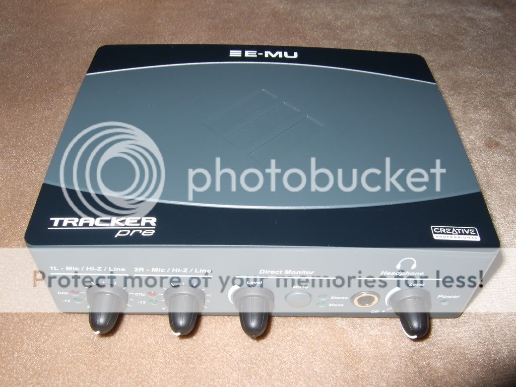
Oh, wow, salas, nice looking device. Looking forward to some measurements, for sure.
Kent, very nice, thank you!
salas said:My EMU Tracker Pre finally arrived! Better measurements on the horizon!
Oh, wow, salas, nice looking device. Looking forward to some measurements, for sure.
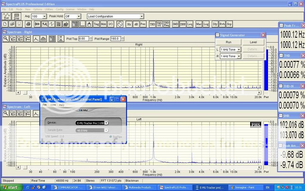
 are you planning to test the shunt?
It goes very low on noise and THD so I will retest some stuff. That picture above comes from someone else. So I don't have more. Its a loop test showing what it can do. I don't know if drivers etc will permit so nice for me too. I will have to find some time soon to get familiar. I have posted before FFT for phono + shunt VS some expensive commercial machine. Black line is the phono + shunt. No 100Hz ripple spike at all. Hum under -90dB (0dB=1V).Off course 50Hz hum is particular to that build only. OK the old card goes only -100dB for noise floor in the highs, but it has more than adequate noise floor in the lows for seeing hum and buzz frequencies. Its 35dB better than the commercial machine (blue line) at 100Hz, and 15dB better for hum. There is a toroid in close vicinity in a small box...it can do better with more gnd care and hum fields care. Like with an external PSU box for instance, lower cable screen resistance and more gnd loop scrutiny.
Attachments
- Home
- Source & Line
- Analogue Source
- Simplistic NJFET RIAA