I am going to try out the simplistic with few bit and pieces left over from my F5 build
I know very little about electronics as such apart from a few adventures with the 8-legged critters.
If you could I will need same help (well loads of it)
I have already a LAC supply for a balanced split passive MC pre (60dB gain) and was wondering what changes I need to make to the Simplistic to use the 24 volts I have available
I do understand that overload margins will be reduced considerably but is more a learning tool for me than else
R2/R18 are essentially in parallel. If using one common, it should be 1.5R not 5.1R. The other questions have been discussed already as I see above.
But is it indiferent ?
I read something about using a common source resistor needing a very carefull matching of the fets.
. The majority of the 6k8 kiwames that I use, measure 6750r so I do not need to use the // 1M
Ricardo is what I mean...nice
")
I don't have used the bleed in the past, probably depends on my old system...sure that power the amp after don't solve the problem...?
thanks Salas, resistor aren't caps
I am going to try out the simplistic with few bit and pieces left over from my F5 build
I know very little about electronics as such apart from a few adventures with the 8-legged critters.
If you could I will need same help (well loads of it)
I have already a LAC supply for a balanced split passive MC pre (60dB gain) and was wondering what changes I need to make to the Simplistic to use the 24 volts I have available
I do understand that overload margins will be reduced considerably but is more a learning tool for me than else
You can't use 24V for a 60dB simplistic. The needed currents for good noise and transcoductance times load to reach gain spec demand the necessary larger load drops.
But is it indiferent ?
I read something about using a common source resistor needing a very carefull matching of the fets.
Split source resistors are there to equalize the currents for not having some hotter fet in the doublet risking some additional noise source. No worry if they aren't well matched there, the total transcoductance counts, and its alike in about same IDSS fets especially when degenerated with Rs. If near enough anyway, a common resistor is all the same. Near matched but no higher than 8mA and 4 red leds should bias well in spec in the discussed schematic. Q5 has large enough degeneration too, so it should average gain for near enough IDSS parts between channels.
Tanks Salas and Ricardo.
Amongst others I have seen simple pre pre with a 10 dB gain again 1 BC 550 and 2SK170
powered by a 7809
Yes I know I am asking for big input and that sound /magic will suffer.
My thinking or lack thereoff was to see what changes are needed as a way to understand a bit more about the circuit and what make it tick.
Yes that is the one 20dB even better tanks a bunch.
"Is the not tweaked for less that" scares me especialy when 2SK170 are so scarce.
Another question are LSK 170 any good
I may let myself loose on same of those whitout feeling guilty before I go for full blown proper build.
"Is the not tweaked for less that" scares me especialy when 2SK170 are so scarce.
Another question are LSK 170 any good
I may let myself loose on same of those whitout feeling guilty before I go for full blown proper build.
To put it in a nutshell, your needs are: 1. To use an existing 24V DC regulated supply. 2. To combine a pre pre and MM circuit if that can be the ticket for not exceeding the 24V supply limit. 3. To use LSK170 Linear Systems. Agreed?
If yes, tell me your cartridge and I will give you a schematic for MM at 24V supply to combine with the pre-pre from the PDF phono guide. You add a stage and a coupler, but you get 2 sensitivities as a bonus and you can use your 24V reg. Linear Systems parts are quite OK as I learn in the forum, me I never used any.
If yes, tell me your cartridge and I will give you a schematic for MM at 24V supply to combine with the pre-pre from the PDF phono guide. You add a stage and a coupler, but you get 2 sensitivities as a bonus and you can use your 24V reg. Linear Systems parts are quite OK as I learn in the forum, me I never used any.
Hi Ricardo have a look at this for now
And Tanks Salas
IMO best way to express my gratitude would be to post same pictures
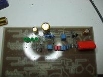
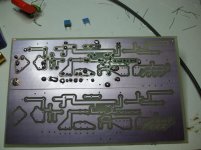
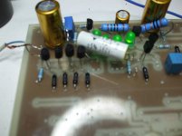
First draft of the PCB stuffed whit what I had available
No matching of measuring of any components apart from the RIAA caps
I have on the board extra space for the prepre and such
The board is built to fit what I have already size is 100 X 160 mm
2 channels on one PCB
And Tanks Salas
IMO best way to express my gratitude would be to post same pictures
First draft of the PCB stuffed whit what I had available
No matching of measuring of any components apart from the RIAA caps
I have on the board extra space for the prepre and such
The board is built to fit what I have already size is 100 X 160 mm
2 channels on one PCB
Attachments
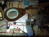
The circuit worked straight away is open on the bench and that magnifying lamp with is neon tube does not do any good to the signals
The supply is my little LM317 bench thing no think special
Same all for the anti RIAA filter just the open box no grounding just bits of wire and crocodile clips for now.
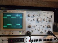
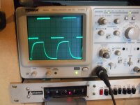
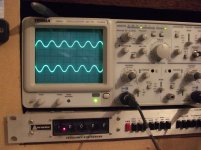
I share Joachim Gerhard opinion that if a square wave looks pretty the circuit should sound good
IMO In all honesty this one (not my effort nothing much there is all Salas merit)
Is one of the prettiest I have seen in a long time please do not forget is all open on the bench and the crapyscope look much beter than what camera and CRT combination shows.
Top trace output from SigGen
Bottom out from Simplistic after signal has passed trough the anti RIAA filter
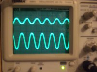
1 KHz 10 KHz and 50 KHz 1 V divisions
1 KHz sine and 1Khz Square at 5 volts division
The supply is my little LM317 bench thing no think special
Same all for the anti RIAA filter just the open box no grounding just bits of wire and crocodile clips for now.
I share Joachim Gerhard opinion that if a square wave looks pretty the circuit should sound good
IMO In all honesty this one (not my effort nothing much there is all Salas merit)
Is one of the prettiest I have seen in a long time please do not forget is all open on the bench and the crapyscope look much beter than what camera and CRT combination shows.
Top trace output from SigGen
Bottom out from Simplistic after signal has passed trough the anti RIAA filter
1 KHz 10 KHz and 50 KHz 1 V divisions
1 KHz sine and 1Khz Square at 5 volts division
Attachments
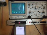
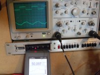
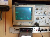
Yes the sine is vell over 15 V peac to peac on a 24 V suply same for the Square
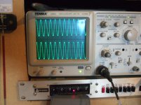
and last one is 10 V gosting duble immage is CRT and camera doing.
Must say I had a good look at a few more at about 100KhZ signall started to srink a bit
But 100 Hz look perfect (crapyscope no good for picture there)
IMO well worth spending same more time and maney for same fancy caps and proper red LED (sorry only had greens).
I am more than happy to post proper PCB drawings and gerbers with Salas permission of course
Tanks Salas
I am measuring circuit as you kindly posted for me on 6832.
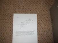
I will need to dig out Anti RIAA circuit.
OF top of my head it is the one with 1.91 K 511K 42sometink K 536R and 60R
MM input was taken at top of 536R MC at top of 60R 40 and 60 dB attenuation
Sorry I am so very untidy I had that in front of me for past 3 years and now that I need it again I can't find it
I will post exactly the circuit and source where I got it from as soon as I find it
In mean time have a couple of links
http://www.audioxpress.com/magsdirx/ax/addenda/media/colin2808.pdf
RIAA backgrounder 6 - Reverse RIAA
I have stuffed the boards with the MC prepre components as on SCH attached.
I have tried to increase gain at first with extra 2SK170s and it did help a bit then placed a pot in series with R1.
It is all still on the bench unscreened and such some how I know already that this is going to stay in the box for a long time once finished.
The RIAA prepre page from your write up
On the board a 150R 3W instead of the 7809 supplied by the 24 V rail
Gain after passive RIAA attenuation (60 dB) with 4 parallel 2SKS R1 =200R
It was 180 on your drawing
And Gain with R1=750R (using a 10 turn 1 K pot)
The source resistors are 33R again is what I have at the movement
Please remember that (for all in general) that I do not have much of a clue on what I am doing so it is easier to put same extra track and holes on the PCB and get rid of it later.
The amazing thing is that it worked the first time.
If once built the changes I have made sound fine I am thinking of little ladder attenuator and Simplistic ploughed in directly on my F5
I normally use only 4 maybe 5 volume settings as follows
Neighbours in
Neighbours out
Her out
And Mental
I am measuring circuit as you kindly posted for me on 6832.
I will need to dig out Anti RIAA circuit.
OF top of my head it is the one with 1.91 K 511K 42sometink K 536R and 60R
MM input was taken at top of 536R MC at top of 60R 40 and 60 dB attenuation
Sorry I am so very untidy I had that in front of me for past 3 years and now that I need it again I can't find it
I will post exactly the circuit and source where I got it from as soon as I find it
In mean time have a couple of links
http://www.audioxpress.com/magsdirx/ax/addenda/media/colin2808.pdf
RIAA backgrounder 6 - Reverse RIAA
I have stuffed the boards with the MC prepre components as on SCH attached.
I have tried to increase gain at first with extra 2SK170s and it did help a bit then placed a pot in series with R1.
It is all still on the bench unscreened and such some how I know already that this is going to stay in the box for a long time once finished.
The RIAA prepre page from your write up
On the board a 150R 3W instead of the 7809 supplied by the 24 V rail
Gain after passive RIAA attenuation (60 dB) with 4 parallel 2SKS R1 =200R
It was 180 on your drawing
And Gain with R1=750R (using a 10 turn 1 K pot)
The source resistors are 33R again is what I have at the movement
Please remember that (for all in general) that I do not have much of a clue on what I am doing so it is easier to put same extra track and holes on the PCB and get rid of it later.
The amazing thing is that it worked the first time.
If once built the changes I have made sound fine I am thinking of little ladder attenuator and Simplistic ploughed in directly on my F5
I normally use only 4 maybe 5 volume settings as follows
Neighbours in
Neighbours out
Her out
And Mental
Attachments
Pics from course of work are always nice. What circuit you measure exactly? The MM one posted above, or the different IDSS MM one from the PDF? Keep in mind we use straight Lipshitz in this one in case you got any extra time constant arrangement in your inverse Riaa.
Straight Lipshitz?
You mean no Numan pole?
Load of controversy about that.
"Poor" Dude place a filter in one of his best selling lates (to stop cutting arm fliing off) and a week later....
A frequency he used was different to start with and 12 dB slope.
B different cutting late had different filters.
At the moment I am realy impressed with the shape of the Square
RIAA acuracy came later with loads of series paralel combination on Resistor and Caps.
- Home
- Source & Line
- Analogue Source
- Simplistic NJFET RIAA