hi Salas, guys
after reading some third- halfway of this wonderful thread I decided to built one for my 0.4mV MC sleeping beauty cart")
First I would like to mod my Azur MM pre (A540p) with njfet input for MC, I once saw one pic of your njfet 0.25mV gain stage only, but lost track of it (the one with parallel sk170 if I'm not mistaken) hope you guys can find it. Just my speedier way to taste njfet before building the complete one
thanks
TeguhPS
after reading some third- halfway of this wonderful thread I decided to built one for my 0.4mV MC sleeping beauty cart
First I would like to mod my Azur MM pre (A540p) with njfet input for MC, I once saw one pic of your njfet 0.25mV gain stage only, but lost track of it (the one with parallel sk170 if I'm not mistaken) hope you guys can find it
. Just my speedier way to taste njfet before building the complete one thanks
TeguhPS
hello
my ps arrived but there is a little problem
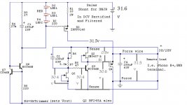
the ps has an output of 31.6 volts and i want to get out from shunt 24volts.
the problem is that i cannot set vout
with the trimmer is either at maximum or minimum value the vout is the same.
i checked the schematic and it`s similar with the one in the pdf.the single difference is that i use 2sk170 instead of 2n5457(q2).all the parts were new.
what should i do?
i attach the schematic with the measured tensions across the circuit.
thanks
my ps arrived but there is a little problem
the ps has an output of 31.6 volts and i want to get out from shunt 24volts.
the problem is that i cannot set vout
with the trimmer is either at maximum or minimum value the vout is the same.
i checked the schematic and it`s similar with the one in the pdf.the single difference is that i use 2sk170 instead of 2n5457(q2).all the parts were new.
what should i do?
i attach the schematic with the measured tensions across the circuit.
thanks
Attachments
the new ps is this http://www.amazon.com/HP-0957-2105-Supply-Module-Adapter/dp/B000M842OU said i wanna buy it a few days earlier
when do you say voltage reference do you refer at Q5 R6 R7 C2 ?
when do you say voltage reference do you refer at Q5 R6 R7 C2 ?
Q3 has 30Vbe.
You have killed your shunt regulator.
A shunt regulator must have a current limiter upstream of the shunt part.
Homework exercise:
Think 31V feeding a 1k0 resistor on to the top of a 24V Zener.
What is the maximum current drawn from the 31V supply?
What sets the limit of that current?
What happens if you short across the Zener?
What is the maximum current with the short applied?
What happens in those situations if you replace the 1k0 resistor with a 10mA CCS?
What is the maximum current drawn from the 31V supply
7ma
What sets the limit of that current?
the resistor
What happens if you short across the Zener?
the entire voltage(31v) will drop across resistor
What is the maximum current with the short applied?
31ma
What happens in those situations if you replace the 1k0 resistor with a 10mA CCS?
this one i don`t know
the 10mA CCS passes a (almost) fixed current over a range of supply voltage.
Let's assume the CCS passes 10mA +-1% over the voltage range of 3V to 40V.
The 10mA CCS when attached to the 24V Zener will see ~ 31V-24V ~ 7V across it.
That 7V is within the operating range of the CCS. It will pass between 9.9mA and 10.1mA by specification.
The Zener will pass that ~10mA current and hold ~24Volts across the output.
Add a short across the Zener. The CCS sees ~ 31V-0V ~31V across it.
That fault condition voltage is within the operating voltage range of the CCS. It will pass ~10mA through the short.
The CCS ensures the circuit is output short circuit proof.
A CCS + Shunt regulator works exactly the same way.
You NEED a current limiter (R or CCS) and Shunt for voltage regulation to happen.
IC = 10 mA, IB = 0.5 mA VBEsat 700 mV from datasheet. guess 0.7v and 0.5 ma are the maximum.to work properly it needs operation points smaller than this ones?
Those are just the test currents for measuring Vbe(sat). Generally an Ic/Ib ratio of 10 is chosen. So as long as the device Hfe is >10, the device will saturate. This is relevant for switching applications.
For linear application, Vbe(on) is more relevant. This is tested in a feedback loop by forcing Ic and servoing Ib until the correct Vce is reached. Measuring Ib gives the Hfe. Measuring Vb gives Vb(on).
Above about 10mA Ic there will be self heating which affects the results. Factory testers use pulse testing with low duty cycle to avoid this.
An NPN silicon transistor BE junction makes a very good zener diode at about 6.5V, Hence the 6V(ish) reverse voltage limit, below Veb.
Sorry - I wandered off a bit!
i have put in series with R1 another 10 ohm resistor because the radiator for those 2 mosfets was getting very hot.now the temperature is lower and the curent draw from the hp ps is 110ma (the preamplifier connected as load on the regulator).i have measured the temperature on the radiator and it has aprox 55 C.if my multimetter reads right should i worry about this?
- Home
- Source & Line
- Analogue Source
- Simplistic NJFET RIAA