Well, in this case we have the same number of active devices for 44dB or 57dB.
So the stepup TX just adds one more component in the signal path
I already experimented a Denon stepup TX with my 48dB riaa and liked it but it adds some hiss (imperceptible).
Off course I needed more cables and the signal passed on several more switches
A friend had hum problems with the same stepup device......
Correct, the same number of "active" devices but the step-up TX is not to be seen like a transistor stage, remember a transformer produces LINEAR distortion and a transistor NON-linear distortion - which is given by it's data.
I never had hiss pronlems with step-up transformers, so what's going wrong? Ground loops or shielding problems of the TX?
Agreed, you need more cables etc... but who cares when it sounds good. BTW, I build my step-up TX into my phono preamps so we have fewer cables and shorter connections.
Ricardo like I told you, come over when you are in Germany and have a listening session here.
The Hi-Fi Press Should Do Some Subsonic Measurements On Their Brains.
Yes indeed Salas
All the Denon figures are useful for (if that even) is to indicate the relative compliance within their own range.
Thanks for the 'real world' figures.
Goldring state the 'static' compliance of my previous cartridge, the 1006 to be:-
24mm/N lat & 16mm/N vert
Which seems to be similar territory to the DL-160 & DL-301 II.
Anyway I still have a bit of 'make up your mind time' left.
I'm going to strip down the Thorens and SME at the weekend hopefully, for a good cleaning, and since I fancy building a whoping great mains filter for it, I will also investigate the electronics, and see if it's worth taking the AC stuff out and building an outboard PSU.
Have also got some plinth painting to do.
What do you think about a bit of a Jackson Pollock rip-off, like John Squire of the roses did his guitars (and the inside of their record labels offices!).
As for the 'Hi-Fi' press, If I had anything to do with it, I wouldn't let 'em waste good trees on it!
Cheers for now Simon

The 160 and 301II should be about 25-30mm/N. That is why the carts work on some seemingly impossible arms. For so many years people get confused and the hi-fi press could do some subsonic measurements on some disputed carts, see what happens. Instead, they wax away lyrically.
Yes indeed Salas
All the Denon figures are useful for (if that even) is to indicate the relative compliance within their own range.
Thanks for the 'real world' figures.
Goldring state the 'static' compliance of my previous cartridge, the 1006 to be:-
24mm/N lat & 16mm/N vert
Which seems to be similar territory to the DL-160 & DL-301 II.
Anyway I still have a bit of 'make up your mind time' left.
I'm going to strip down the Thorens and SME at the weekend hopefully, for a good cleaning, and since I fancy building a whoping great mains filter for it, I will also investigate the electronics, and see if it's worth taking the AC stuff out and building an outboard PSU.
Have also got some plinth painting to do.
What do you think about a bit of a Jackson Pollock rip-off, like John Squire of the roses did his guitars (and the inside of their record labels offices!).
As for the 'Hi-Fi' press, If I had anything to do with it, I wouldn't let 'em waste good trees on it!
Cheers for now Simon

I'm stuck :-(
Hi all,
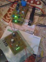
I run through the topic more or less and started to build a phono with shunt.
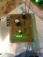
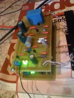
Please find version below on picts. With the early Salas shunt ( changed the zener to 36V) it worked with an audible hum but did well. So i went forward on making a new shunt (r6 mod, led vref ). The shunt is working R1(10ohm) makes 1,9V so i have approxx 200mA but the Riaa sound on very low volume.
Some changing in components was made in riaa that i orderd riken and prp resistors and low esr elkos. Since 2.4k in prp was not available it was substituted with 2.2k.
With the other shunt or with a lm317 the volume was on the right value.
I am totally down and thinking of giving up.
Any advice would be appreciated.
Karesz
Hi all,
I run through the topic more or less and started to build a phono with shunt.
Please find version below on picts. With the early Salas shunt ( changed the zener to 36V) it worked with an audible hum but did well. So i went forward on making a new shunt (r6 mod, led vref ). The shunt is working R1(10ohm) makes 1,9V so i have approxx 200mA but the Riaa sound on very low volume.
Some changing in components was made in riaa that i orderd riken and prp resistors and low esr elkos. Since 2.4k in prp was not available it was substituted with 2.2k.
With the other shunt or with a lm317 the volume was on the right value.
I am totally down and thinking of giving up.
Any advice would be appreciated.
Karesz
Attachments
Do you have an oscilloscope? If there is oscillation at the output of your new shunt, then signal volume goes down and hum appears. Do you have hum also? Any pictures? Delete C9 and make R7 1k2 for a start. Maybe there is interaction by the cap or the buffer overrun with current especially when with a smaller R11.
P.S. What is the mV reading across your new shunt's R4?
P.S. What is the mV reading across your new shunt's R4?
Yes I have scope and hum also but signal seems stronger then hum. I'm working now so any try will be place lately afternoon at home.
I took shots yesterday but forget to bring cable for phone :-(.
For base i used ikoflexer "squared" pcb and in place of R6 i changed to 2sk170.
All fet's IDSS are between 7 and 8. IRFP's on sink generating light warm.
I did a measure last night on the shutn output on positive side connected a 0,47 ohm 5W resistor and mesured Voltage and get 50mA on it.
As i get home i will make and upload photos. What should i measure with scope?
Anyway sorry for my neewbie question and thanks for your quick reply.
Karesz
If you will just hook up the scope between B+ and gnd, setting the scope in AC mode, you should see a straight 37V line. If you see waves or other weird things then the power is oscillating. Make sure about the orientation of the 2SK170 you substituted R6 with it has pin 1 towards +Vout line. In general don't worry, you have built two very classic and repeated circuits around here, and its impossible they will escape us and not work perfectly. Don't forget to take out C9 and make R7 1k2 on the phono. Do you have 7mA IDSS on that phono too? We will have to check out some bias voltages when you will be near it later. All drain to earth points and Q3's collector to earth so to see if there are issues there. With 0.47K dummy across the reg's output you should get nominal 78mA through it and the Vout should stay at 37V.
So in the shunt across R4 i got 66.6mV. Scope in AC mode i saw straight 37V in 10 V/div but in 5mV V/div the line became noise or something. Yesterday i had no possibility to buy 1k2 for R7 on the phono so tried R11 with the original 2k4 and it lowered the volume on that channel. Pictures attached.
My filter section before the shunt is 2 10mF cap and a 22R 2W resistor between them on the posistive side.
Karesz
My filter section before the shunt is 2 10mF cap and a 22R 2W resistor between them on the posistive side.
Karesz
Attachments
Nice and clean. Good component quality balance. Now lets see. First that 5mV/diV line became ''noise or something'' must be showing some trouble in the regulator. First I would change the Zener with a 2.2k+3k3 in series. Will give about 37V again for 6.6mA. That will overcome some doubt about the Zener quality. Second I would surely change R7 to 1k2 in both phono channels. Changing level from 2k2 to 2k4 dropper seems its in stress there. Is the Idss 8-9mA everywhere on the phono channels? Can you measure some voltages on it? And does it play ''normally'' with a different regulator, either the previous or a chip regulator?
P.S. The reg board I don't remember it exactly but I see enough distance between the BC550 and its 2SK170 load. Was it originally made for a resistor load? Because the active load pushes the gain up a lot and it could be low level oscillating if not near together. I would hack the pcb line towards 550's base and put a 47R base stopper intimately to its base in line. Also use coaxial shielded cable on phono inputs.
Although the phono played on normal volume but had some audible distortion with chip regulator or previous shunt.
2sk170 are in range 8-9mA everywhere in phono. Measuring voltage on jfet means Vgs ?
Regarding the shunt you want me to take Q6 and R5 closer to bc550 p2p?
P.S. This phono worked well with a slight hum before i have replaced resistors and capacitors with quality ones.
2sk170 are in range 8-9mA everywhere in phono. Measuring voltage on jfet means Vgs ?
Regarding the shunt you want me to take Q6 and R5 closer to bc550 p2p?
P.S. This phono worked well with a slight hum before i have replaced resistors and capacitors with quality ones.
Maybe some fet got damaged when making the changes. 1st. Put a 2k2+3k3 or 10k//12k in place of the Zener. 2nd. Test fets drain voltages to ground and Q3 collector voltage to ground on both phono channels and post them here.
3rd. See again if its the same on the scope after you substituted the Zener and we will see about p2p changes.
3rd. See again if its the same on the scope after you substituted the Zener and we will see about p2p changes.
Hi Salas,
Zener changed to 5k trim + 1k1 and set to 5k5. I see approx. the half of noise.
Q1=7.46 Q1=7.45
Q2=3.06 Q2=3.64
Q5=30.4 Q5=29.18
Q3=8.18 Q3=8.17
New experience. Tried with lm317 reg and volume was on the same level (very low)
directly connected to power amp. So i realized that lm317 Vout was 36.5V so started to increase it and at 40V i got a well audible sound.
P.S. R7 replaced to 1k1 (not 1k2 you suggested because i don't have 1k2. It is ok or sholud i replace to 1k2?)
Karesz
Last edited:
It had very low voltage headroom in the cascode and on second stage your numbers show me. That is why you got sound when you added B+. Your leds appear strong, maybe at 8.1V, take one out from each quad, short its pads. You should be left with 3 glowing leds per channel. Your 2nd stage fets are stronger, or your R6 is 22R. 1k1 is a good R7 value. If with stronger fets its not bad, but make R6s into 100R trimmers (middle leg connected to ground leg, top leg to source pin). Don't throw away your old R6s, recycle them as in the picture so they are helpful with Q6's dissipation. Set trimmers at 33R, connect to the 37V (exactly set) shunt, turn the R6 trimmers for 8V at Q2's drain to ground. Should be doing OK with those numbers hopefully. Also tell me the new numbers on Q1 & Q5's drain to ground after that. Use coaxial shielded cable for input. What is your test cartridge and what load did you use for Rload? Also is your C3 a combination of polysterenes and what is the value of its main component?
Attachments
ARMAGEDDON is a simplistic power supply !
I checked it out as I had no idea what it was.
Also the Linn Lingo, I don't reckon there are too many clones of that about you'd have to be a brain surgeon to clone that, it looks like there's more part's in it than my computer !
I'm sure you've seen inside, it's a darn big torroid in a tin can.
A $2000 wall wort. It doesn't even have any of those impossible to get 2SK170's in it.
Anyway I'd like to have one, if only for the fact it's one of the best product names I've ever come across. You'd never find 'The Armageddon Bookshelf' in Ikea.
Salas, I know we all want transformers in seperate boxes for every thing, and I must say transformers in the same case as the tube mic-pre I'm doing at the moment is worrying me a bit.
How sensitive is the simplistic JFET preamp in reality, would I be likely to spoil its performance if it was down one end of a 19" case and the transformer was at the other ?
My other option is to power the TT and simplistic from a geddon clone. I'm sure a weedy TT motor & a preamp wouldn't make much of a dent in a 500va torroid. I could even get a 1000va one, just to take it to extremes!
Also I wondered if you or anyone else reading had am opinions about non magnetic v. steel cases. I some times scratch build cases or use aluminium out of habit as its way easier to work on. But am looking at a nice alu/steel case for the simplistic and wondering if steel cases help magnetic fields to spread out more ? Got quite a bit of stuff on the go at the moment so am gathering parts, drawing and will work on a PtoP layout for it soon but may well do reg on vero-board as no potentialy big parts to swap in and out.
Cheers Simon......
Hi thanks for recommending ARMAGEDDON to me.a Geddon
I checked it out as I had no idea what it was.
Also the Linn Lingo, I don't reckon there are too many clones of that about you'd have to be a brain surgeon to clone that, it looks like there's more part's in it than my computer !
I'm sure you've seen inside, it's a darn big torroid in a tin can.
A $2000 wall wort. It doesn't even have any of those impossible to get 2SK170's in it.
Anyway I'd like to have one, if only for the fact it's one of the best product names I've ever come across. You'd never find 'The Armageddon Bookshelf' in Ikea.
Salas, I know we all want transformers in seperate boxes for every thing, and I must say transformers in the same case as the tube mic-pre I'm doing at the moment is worrying me a bit.
How sensitive is the simplistic JFET preamp in reality, would I be likely to spoil its performance if it was down one end of a 19" case and the transformer was at the other ?
My other option is to power the TT and simplistic from a geddon clone. I'm sure a weedy TT motor & a preamp wouldn't make much of a dent in a 500va torroid. I could even get a 1000va one, just to take it to extremes!
Also I wondered if you or anyone else reading had am opinions about non magnetic v. steel cases. I some times scratch build cases or use aluminium out of habit as its way easier to work on. But am looking at a nice alu/steel case for the simplistic and wondering if steel cases help magnetic fields to spread out more ? Got quite a bit of stuff on the go at the moment so am gathering parts, drawing and will work on a PtoP layout for it soon but may well do reg on vero-board as no potentialy big parts to swap in and out.
Cheers Simon......
I believe you found DIY Geddon info if you Googled it. The simplistic can live with an R-Core in same roomy box if the high voltage cabling is twisted and tucked away in opposite corner from the phono and RCA's but best is two boxes. It can do OK if at 50cm minimum distance if EI or Toroid is used. Make that 1m if we are talking Geddon league toroid. If the boxes are ferromagnetic they keep the fields in much better than Alu and they can rest side by side. The shunt reg will never mind its rectification and filtering being fed by another secondary from a Geddon Tx, I don't know if the TT will feel anything, Geddon gurus would know that I suppose. 
- Home
- Source & Line
- Analogue Source
- Simplistic NJFET RIAA