I wish I had the old plinth. Looked and worked much better than this one. They were classy looking tables.
Would you P.M. me with the motor supply mods you did, I am still using the originals.
Thanks for the compliment on the case. I am seriously considering breaking this thing into two chassis. Working on version two of the pc boards as well. This time with 100% star ground and reduced trace size and lengths to minimize capacitance and potential issues.
I am in doubt you have issues with your current build. Try to loop some other DUTs to see if its a measuring trend. You have shown much better harmonic noise before for the same box. Mind you if you had 60Hz in the -40dB on 1V 0dB graph, and all those multiples, it would be humming and buzzing like a bad guitar amp when on the audio system.
I ran a quick check on my preamp and it did not have the same issue. Noise floor on the preamp is about -105dB though.
I think the main problem is mostly in the measurement system. Certainly don't hear hum at that level. The input does not like to be referenced to ground external to the chassis. The TT isn't.
The lack of a true star ground has been nagging on me so I did want to layout the board better at some point. I can't play the TT tonight so it is as good as anytime to do it. I would also like to drop the noise floor if I can with this.
Salas,
How would/did you do your divider? Mine is enclosed in the rca connection housing.
With the divider attached for calibration, the measurement systtem is dead quite. The RIAA also quites down with only a trace of the harmonics with the input shunted to ground via 50R termination.
How would/did you do your divider? Mine is enclosed in the rca connection housing.
With the divider attached for calibration, the measurement systtem is dead quite. The RIAA also quites down with only a trace of the harmonics with the input shunted to ground via 50R termination.
Mine's in a copper tube. One end is female RCA the other is male RCA. Another one I made in a metal TRS that goes to Tracker's out, from there RG179 to RCA.
I have seen using a pseudo balanced out giving harmonic noise to a ''real'' XLR input some times. If the Riaa reads no serious harmonic noise when with a shorted input, then there isn't any created by it alone. Simple as that.
I have seen using a pseudo balanced out giving harmonic noise to a ''real'' XLR input some times. If the Riaa reads no serious harmonic noise when with a shorted input, then there isn't any created by it alone. Simple as that.
TRS?
The Riaa is quite well behaved with the input shorted. I will go back back to my laptop system tomorrow and run some tests. I found ground lift switches on the bottom of the EMU0404 box. That may help. I hope I can get the direct through noise floor down close to your level. I really want to measure how quite this thing is.
The Riaa is quite well behaved with the input shorted. I will go back back to my laptop system tomorrow and run some tests. I found ground lift switches on the bottom of the EMU0404 box. That may help. I hope I can get the direct through noise floor down close to your level. I really want to measure how quite this thing is.
Tip Ring Sleeve. Looks like a guitar plug. The Emu Tracker is for home studio and has outputs like that. Noise spec is professionally measured only with input shorted to ground. Its a standard. If shows low like that, search not inside the box.
With your gain, noise floor in my builds is less than -100dB at 20Hz, -140dB at 20kHz. You can get from none to -90dB or -80dB mains fundamental depending on isolation, given no ground loops.
*Ref 0dB 1VRMS out.
P.S. Can I see the phono's floor with shorted input with your current measuring setup?
With your gain, noise floor in my builds is less than -100dB at 20Hz, -140dB at 20kHz. You can get from none to -90dB or -80dB mains fundamental depending on isolation, given no ground loops.
*Ref 0dB 1VRMS out.
P.S. Can I see the phono's floor with shorted input with your current measuring setup?
I thought TSR was that wasn't sure, I have always called it 1/4" but I didn't really know the correct terminology.
My EMU and MAudio are TRS as well. The EMU is actually TSR out and multi (TSR, XLR, or TS,) connection in. TS being Tip Sleeve.
I will work on the measurement in the morning.
P.S. Check your email
My EMU and MAudio are TRS as well. The EMU is actually TSR out and multi (TSR, XLR, or TS,) connection in. TS being Tip Sleeve.
I will work on the measurement in the morning.
P.S. Check your email
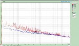
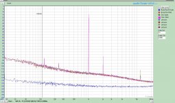
I didn't expect this. Attached are comparisons between Version1 and Version2. I turned the system off/rebooted and it repeated.
All scales relative to 0dBs = 1Vrms
Red curves are the Version 1
Blue Curves are Version 2
There is no difference in set-ups other than moving the leads back and forth. Seems version 2 is quieter.
Version 2 does have a slightly higher second order harmonic probably a resistor difference between boards that needs tweeked.
Attachments
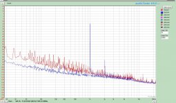
OK, bcs I wondered about that needle above 10k. I see artifacts like that when TVs are on around, but it can also be the FFT and its decimation ratio. I just took one from my 61dB build, the one that you saw with the 120VA R-Core inside the mid width black box. The other channel was still attached on the TT and the preamp. Seeing that, yours looks OK too. Input 0.25mV.
Attachments
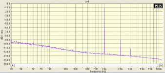
In this configuration, I am looking at version two of the pc board. Version one is not looking bad either but not presented as there are too many graphs.
Blue is shorted input to M-Audio to get a feel were the measurement noise base is.
Red is connected to RIAA with its input shorted
Olive is connected to RIAA with the input connected and no signal
Pink is 0.3mV input
All curves referenced to 0dB = 1Vrms.
In this test I cut out the torroid and moved it about 1 meter away. Secondary is fed back into chassis via twisted 14awg wire. PS rectifier and filter still mounted in existing chassis as before. That will be the next move. Covers are on.
Conclusion was my torroid was lighting the place up inside the chassis. With the torroid in the chassis, I was finding that simply placing the inner cover on was increasing the harmonic spray of 60Hz
P.S. I am still using the pmillet interface to drive the input. WIll try without to see if it makes a difference
Attachments
Like reflecting the hum field back in. Now if you listen to it like that until your R-Core arrives, it should suddenly have a mellower tone with the Teflon caps too. Sure there is still more resolution to have if possible in the FFT bcs the 3rd harmonic is only poking out a bit.
Good work.
Good work.
I have mains exposed. Saw a thread in the tube section about cats. Same issue here. They especially like the roundy round of the turntable. If the cat hits the mains, it won't bother me as much but the kids won't like it.
His name by the way is Toast. We have a second cat named Spare. We live on a small farm so we needed back-ups. We tend to go through cats here, gave these two names to reflect history and they actually have survived. Go Figure. And no you can't make this kind of stuff up.
His name by the way is Toast. We have a second cat named Spare. We live on a small farm so we needed back-ups. We tend to go through cats here, gave these two names to reflect history and they actually have survived. Go Figure. And no you can't make this kind of stuff up.
- Home
- Source & Line
- Analogue Source
- Simplistic NJFET RIAA