Good Morning,
so i did match some 2sk170bl and got four pairs with idss 6,61mA.
Would you please recommend a circuit including salas-reg-psu to
me to ideally play with my lyra dorian cartridge as asked some post-
ings before.
Greetings Ulf
Use your matched ones for Q1,Q2,Q3,Q4. I fixed it for double njfet first stage so you make full use of your available pairs. Find two near ones for Q7, within 1mA any idss from 6-10mA, not critical. 2V green LEDS everywhere. In the PS use for Q2 your lowest IDSS.
Make sure that the idss you mentioned is correct. I use the 9V battery and current mode DVM in series with no resistor simplest method and is always spot on. Good luck.
Attachments
Salas,
you´re great, thanks allot. I´ll build this pre then ;-)
One question at the moment: What jfets should be
thermally bonded? Q1/2 i guess
What about q3/4 then? And psu fets, should they be
thermally be bonded?
Do you have an idea what´s the Zout of this phonopre?
Greetings ulf
you´re great, thanks allot. I´ll build this pre then ;-)
One question at the moment: What jfets should be
thermally bonded? Q1/2 i guess
What about q3/4 then? And psu fets, should they be
thermally be bonded?
Do you have an idea what´s the Zout of this phonopre?
Greetings ulf
No one FET needs to get bonded. Q1, Q2 have highish sharing source resistors they won't current hog, Q3, Q4 run different currents, are different stages, and PSU has no stage pair either. With your IDSS, Zo should be around 40 Ohm. You should expect around 0.01% THD second harmonic dominated, and good background silence. Will be nice to know your impressions after all works well, since you got so many carts, arms and phono stages. Good luck.
Salas,
How far back in this thread do I have to go to get what is needed to build and inderstand this design? The size of this thread is daunting.
Thanks
I'm not Salas,
Go here post 2331 psgr acrobat rader attached files: http://www.diyaudio.com/forums/analogue-source/129126-simplistic-njfet-riaa-234.html#post1931376
Waiting to help.
Felipe
Last edited:
R3 disconnects the first stage if you take it out. So it comes from first stage.The voltages you posted are pretty OK.
Those are hum frequencies. Is it wired for signal input and output with coaxial? Also take out the 220uf over the leds and see if it has anything to do. If there is 0.1uf across B+ on phono take that out too.
Hello
Today I just removed C1-220uF and I get same result. So I start to remove some other components.
1º I removed ground from D1-D4 and R2V and put a wire to star ground - no
effect
2º R2V replaced by fixed resistor - no effect
3º Remove Q3 (led's still on) - no noise
4º change Q3 to japanese equivalent - no effect-noise
5º Q1 replaced by one with Idss 10mA - still the same - noise
Did anyone tried this 56db version ?
Everybody does this cascode with a Q3. Its in the pdf for over a year now. Every different schematic you see member's made is this one backbone. Franz made it recently for 60dB on horn speakers for example, said many times its very silent. I have one 61dB playing with even double Q3 and 4 fets. Mystery is your case. But if you solve it by removing q3 and you still like it, its a way. Having made it cascode and non cascode, the former has better analysis. Lets think a bit, whatever comes from q3, can be 2 things. Either noise at its base (what kind of leds you use?) or easier EMI or magnetic field pick up since the cascode ups the impedance and opens the bandwidth. How far is the transformer, and do you have incidents of RF interference with other machines in your area?
P.S. One thing I see reviewing again your pcb, is that the LEDS are located far away from Q3's base. I hope that the track's inductance does not put it into oscillation. Stick a 33R base stopper on it, hard wired on the base pin, very small lead, AFTER the smoothing 220uF cap.
P.S. One thing I see reviewing again your pcb, is that the LEDS are located far away from Q3's base. I hope that the track's inductance does not put it into oscillation. Stick a 33R base stopper on it, hard wired on the base pin, very small lead, AFTER the smoothing 220uF cap.
Hi Merlin... cannot open any document with the link inside the pdf
Hi Rcruz, here is the pdf information metallized & film both teflon:
$15 each
Custom-Balco Data TexCap Data
TEFLON FILM/FOIL: F=1%, H=3%, J=5%, K=10%, M=20% Picture
.0001, +20/-10, 1000V, Custom TFHT
.001, J, 200V, TexCap 43
.0015, G, 200V, TexCap 200GGS
.002, J, 200V, TexCap 43
.0022, J, 200V, TexCap 43
.0025, G, 400V, TexCap 200GGS
.0027, J, 200V, TexCap 200GGS
.0033, J, 200V, TexCap 43
.006, J, 200V, TexCap 200
.01. J, 200V, TexCap 43
.01, K, 200V, Custom TFHT
.015, J, 200V, TexCap 43
.015, F, 200V, TexCap 43
.015, K, 400V, TexCap 200GGS
.018, J, 200V, TexCap 200GGS
.02, J, 200V, TexCap 200GGS
.022, J, 200V, Balco HT2
.022, K, 200V, Custom TFHT
.023, J, 200V, TexCap 200GGS
.027, K, 200V, TexCap 43
.027, K, 50V, Balco RTWG wrap-n-fill
.03, F, 100V, Custom TFHT
.033, J, 200V, TexCap 200
.047, J, 200V, Custom TFHT
.05, J, 100V, TexCap 200
.05, J, 100V, Custom TFHT
.056, J, 200V, Custom TFHT
.18, J, 200V, TexCap 200GGS
NOTE: Some of these capacitors have solderable/weldable leads. They solder easily, but require extra heat.
$15 each
Custom-Balco Data TexCap Data
METALLIZED TEFLON: F=1%, H=3%, J=5%, K=10%, M=20% Picture soon
.02, J, 200V, TexCap 83
.02, F, 200V, TexCap 83
.047, K, 400V, Custom TMHT
.06, K, 400V, TexCap 83
.10, J, 50/100V, TexCap 83
.10, K, 200V, TexCap 83
.18, J, 50V, TexCap 83
.20, J, 200V, Custom TMHT
.22, K, 400V, Custom TMHT
.25, K, 200V, TexCap 83
.25, K, 200V, Custom TMHT
.50, J, 50V, TexCap 83
NOTE: Type 83 is not in the Texcap datasheet. Samples were opened to verify metallized teflon. Teflon has a white tint and stretches easily. Other dielectrics do not have these qualities.
You also can try looking at the web: Surplus USA Film Capacitors Teflon Polycarbonate Polyester Polypropylene
If you can enter & you need the datasheet of any cap let me know?
Thank you so much Merlin
Your welcome RCruz, if you have problems to buy or needs anything else let me know to help you.
I'll show you the populated pcb when ready. The pcb alone won't tell you anything. It's very similar to the design I post months ago: dual SSSRegs v1.2 + SNJfet Riaa 60dB in a 21 x 9,5 cm board@massimo
Could you post photo with etched pcb & schematic?
I'll show you the populated pcb when ready. The pcb alone won't tell you anything. It's very similar to the design I post months ago: dual SSSRegs v1.2 + SNJfet Riaa 60dB in a 21 x 9,5 cm board
Could you sell/trade me one dual SSSRegs v1.2 + SNJeft RIAA 60dB please?
First of all I have to check if it worksCould you sell/trade me one dual SSSRegs v1.2 + SNJeft RIAA 60dB please?
later could be, maybe in a special version with "Forza Inter" etched on it Or do you prefer "We are the world champions" ? First of all I have to check if it works
"Forza Inter" sounds very good & similar to "Força Barça", "we are the world champions" sounds like a Queen song....
Everybody does this cascode with a Q3. Its in the pdf for over a year now. Every different schematic you see member's made is this one backbone. Franz made it recently for 60dB on horn speakers for example, said many times its very silent. I have one 61dB playing with even double Q3 and 4 fets. Mystery is your case. But if you solve it by removing q3 and you still like it, its a way. Having made it cascode and non cascode, the former has better analysis. Lets think a bit, whatever comes from q3, can be 2 things. Either noise at its base (what kind of leds you use?) or easier EMI or magnetic field pick up since the cascode ups the impedance and opens the bandwidth. How far is the transformer, and do you have incidents of RF interference with other machines in your area?
P.S. One thing I see reviewing again your pcb, is that the LEDS are located far away from Q3's base. I hope that the track's inductance does not put it into oscillation. Stick a 33R base stopper on it, hard wired on the base pin, very small lead, AFTER the smoothing 220uF cap.
Probably I didn't make my self clear ( sorry Salas), When I removed Q3 I just want to remove it, and also Q1 from the signal path, so I listen to it with Q6 and led's working(only low level HUM), but of course no sound !
As you say, noise could come from Q3, and how about Q1?
I'm using four yellow led's, all the same ref, they give me Vref within the values (aprox 7.6V).
For the transformer, it's a R-core, 30cm away ( already tried 80 to 90cm).
I changed to a new ref led's and move them near Q3, installed a 33R base stopper, but noise is still there.
P.S.Right now I'm typing this and listening the phono, and sounds AMAZING ( except between tracks at medium volume)
Attachments
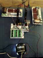
Hey, box it first. You can't know when having a 56dB gain circuit in the open.
P.S. Those black cables from channels go to the main filter cap's earth. Should go to the reg's terminal caps (-).
Thanks Salas
I will try that also
Probably I didn't make my self clear ( sorry Salas), When I removed Q3 I just want to remove it, and also Q1 from the signal path, so I listen to it with Q6 and led's working(only low level HUM), but of course no sound !
As you say, noise could come from Q3, and how about Q1?
I'm using four yellow led's, all the same ref, they give me Vref within the values (aprox 7.6V).
For the transformer, it's a R-core, 30cm away ( already tried 80 to 90cm).
I changed to a new ref led's and move them near Q3, installed a 33R base stopper, but noise is still there.
P.S.Right now I'm typing this and listening the phono, and sounds AMAZING ( except between tracks at medium volume)
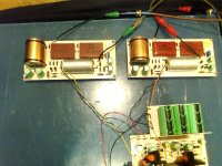
Neat work congratulations, what output caps, resistor are you using?
Neat work congratulations, what output caps, resistor are you using?
Hello Merlin
Thanks for your kind words
Caps:
Cout - Obbligato Cu 3.3uF
C3 - Lemco silver mica 0.016uF
C2 - Lemco silver mica 0.047uF
C4 - Aluminum / teflon russian FT-3
Resistors
All of them carbon composition
R11 - Allen Bradley
R3 -Aircospeer
Rest -Tyco
- Home
- Source & Line
- Analogue Source
- Simplistic NJFET RIAA