ok, i just finished my second signal processor. i recently got a subwoofer for a larger project, and just wanted to build a simple crossover to allow me to add it basically to my computer speakers. it is a butterworth, 2nd order lowpass using a sallen-key topology. It opperates off of a single +12V computer power supply. there is a voltage devider using resistors, metal film, 2.5kohm each. the middle is run to a + input on the op amp and the - input is run to ground. a capacitor is placed between these 2 inputs as well.
an input buffer is then used. a capcitor runs to 2 resistors, one 100kohm resistor runs to the virtual ground from the first opamp. the other resistor is run to the + terminal of the opamp. the - and output of the opamp are shorted. it looks like the buffer in this circut: http://sound.westhost.com/project09.htm
ok, the op amp is a lm837n quad low noise opamp. i got it for $0.25 and figured it would be ok. all resistors are metal film. the resistors on the lowpass are 37.4kohm. the larger capacitor is 98nF, and the smaller capcitor is 48nF. both of these capacitors are polyester. the output from the filter runs to a 240ohm resistor and then a 1uF mylar capacitor. the opamp is bypassed with a 10uF capacitor between 12V and ground, and a 100nF monolythic cap between 12V and ground.
the circut has a problem with making crackeling sounds. also the output is low. the signal does pass if i increase the gain on the amp. also, it seems not to act as a lowpass all too well, the passed signal is more than just bass. what causes the crackeling? just too low voltage rails? I had built a lowpass filter before using 1 741 and it didn't have this problem.
1) The computer power supply is full of noise, but you are stuck with it. As you are trying to operate the op-amp in single mode, however, some of the noise is working its way to the input. If you had a scope you could probably see a switching pulse some tens of millivolts being fed to the amp. While the noise is higher frequency than audio, it combines with the audio to generate sidebands, one one of which is lower than the sum of the noise + signal, one of which is higher than noise + signal. You can <b>try to filter</b> the 12V output with both inductor and capacitor, but these switching pulses are nasty critters. For a lot of reasons, single ended will work much better with an opamp designed for this purpose.
2) A trick to get a lower noise output firts used in the earlier days of switching supplies was to use a linear post regulator, like an LM317 after the SMPS output. Figure that an LM317L will handle about 100ma which is plenty for this application, but it needs a few milliamps to work correctly. You lose some efficiency with the post regulator -- try 1.7K/270R values for about 8 volts out. or 2k/270R for 9.2Vout and remember to use a tantalum cap on the output.
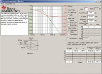
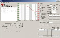
3) Here's a snapshot from TI's Filter Software which is freeware from their site:
2) A trick to get a lower noise output firts used in the earlier days of switching supplies was to use a linear post regulator, like an LM317 after the SMPS output. Figure that an LM317L will handle about 100ma which is plenty for this application, but it needs a few milliamps to work correctly. You lose some efficiency with the post regulator -- try 1.7K/270R values for about 8 volts out. or 2k/270R for 9.2Vout and remember to use a tantalum cap on the output.
3) Here's a snapshot from TI's Filter Software which is freeware from their site:
Attachments
theChris said:It opperates off of a single +12V computer power supply. there is a voltage devider using resistors, metal film, 2.5kohm each. the middle is run to a + input on the op amp and the - input is run to ground. a capacitor is placed between these 2 inputs as well.
Do you realy mean the - input is connected to ground? If that is true the output will be forced high. The - input should be referenced to the same voltage divider as the + input. It can be isolated by a high value resistor and AC referenced to ground with a cap if the - input needs to be zero signal referenced.
Or if this is a buffer the - input should be connected to the output, but you knew that
Later
Bruce

hmm. i don't think that was it, the voltage on that is a pretty constant 5.19V to 5.20V (from a 10.40V source). now that i'm finally back on campus i plan to test it with some equipment to see exactly how the voltage affects it. i'm getting the feeling that moving to a higher voltage, like +-15V would be the best bet.
I will look into your suggestion, do you mean basically shorting the + and - inputs to each other and the middel of the voltage divider?
plus i think the filter itself didn't work. i'm going to check to make sure the "18kohm" resistors are actually 18kohm and not something else. it doesn't seem to block anything until about 10kHz. the prediceted point was at 60hz... and i have had mis-bagged resistors before, like 15ohm resistors in a 5kohm bag. i quickly found that error when i burnt myself on one of em...
i hate the evil gremlins. they sneak into my mind and change the schematics! oh. oh i am un beleivibly mad. well. i guess you _could_ understand!
i see i messed up the voltage devider. sad thing is i built one with the voltage devider correctly made and decided that it wasn't correct before testing or finishing it. i swear there is some kinda gremlin that does this to me. well, maby not a gremlin, maby a hobgoblin or such...
ok, i see the error, i don't think it will be that hard to fix either.
ok, now i've got the subwoofer in my room, and a 60W amp. definately not the tremendous output i was hopeing for, but on a good note the woofer can barely be heard outside the room, so i'm less likely to get a noise violation.
however the filter i built is having issues. it plays the sound about right i guess for a 60hz crossover point, but there is a funny sound that plays at the same time. is this due to the low voltage or something else?
however the filter i built is having issues. it plays the sound about right i guess for a 60hz crossover point, but there is a funny sound that plays at the same time. is this due to the low voltage or something else?
i'll have to try that, it may just be this ground loop phenomenon i've been hearing about.
actually i bult a second filter, 3rd order at 80hz, i like it better. not audiophile good, but it allows me to hook the sub up decently with the computer speakers. i don't have a 9v laying around sadly.
it's bizzar, you can't hear the sub out of room, and if you stand near a wall, the quality kinda goes away, but at my computer, the sound is good.
well, i chose 80hz because my computer subwoofer kinda goes down near that frequency, and when i build my finished project, the 6.5 mid-woofers will be able to reach 80hz if i use a butterworth filter. (and lets be honest, there is no way i'm going to be able to build a phase perfect design without knowing where the subwoofer will be located in room!)
i'm gonna post a list of all my qestions soon.
i'm gonna post a list of all my qestions soon.
If I could add some input ....bass is non directional and the longer the standing waves are is better. i would place the sub in the corner of the room furthest from you if possible...I was able to get a +3dB boost on my little 6 inch sub....and that was recorded with a 2000 dollar sound level meter set at 80 hz
Cheers!!The DIRT®
Cheers!!The DIRT®
"If I could add some input ....bass is non directional and the longer the standing waves are is better. i would place the sub in the corner of the room furthest from you if possible...I was able to get a +3dB boost on my little 6 inch sub....and that was recorded with a 2000 dollar sound level meter set at 80 hz
Cheers!!The DIRT®"
-yeah, the woofer in underneat a bed and in the corner, or close to it at least.
"the reflections cancel and add, leading to power loss or distortion."
-moving around in the room is kinda odd. but the bass is good in my listening area.
Cheers!!The DIRT®"
-yeah, the woofer in underneat a bed and in the corner, or close to it at least.
"the reflections cancel and add, leading to power loss or distortion."
-moving around in the room is kinda odd. but the bass is good in my listening area.
- Status
- This old topic is closed. If you want to reopen this topic, contact a moderator using the "Report Post" button.
- Home
- Source & Line
- Analogue Source
- lowpass filter failure