another question
Hi
I renewed this thread because I do not want to start a new thread.
I bought Kenwood ST-1100 and started mod it.
Please look at the schematic of analogue output filter and amp.
I want to remove C94,100 (short).
before those caps is 0V.
What do you think, is it safe to make shorts? Maybe those caps are the part of High Pass Filter?
Is there a danger to appear DC after shorting?
Attachments
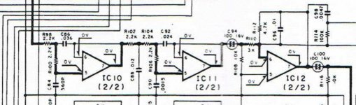
They are safe to short out and do not form any part of the filter circuits. Just confirm afterwards that there really is 0.00 volts DC at pin 7 of the final opamp. Even if there is a slight voltage (say less than 20mv) it is not necessarily a problem as most preamp inputs are AC coupled anyway.
You might find replacing the opamp with a FET type reduces the offset to zero as long as the input (R98) is AC coupled (in the part of the circuit not shown) or has a true 0.00 volt DC on it anyway. For something like this it could well be an upgrade too.
You might find replacing the opamp with a FET type reduces the offset to zero as long as the input (R98) is AC coupled (in the part of the circuit not shown) or has a true 0.00 volt DC on it anyway. For something like this it could well be an upgrade too.
They are safe to short out and do not form any part of the filter circuits. Just confirm afterwards that there really is 0.00 volts DC at pin 7 of the final opamp. Even if there is a slight voltage (say less than 20mv) it is not necessarily a problem as most preamp inputs are AC coupled anyway.
You might find replacing the opamp with a FET type reduces the offset to zero as long as the input (R98) is AC coupled (in the part of the circuit not shown) or has a true 0.00 volt DC on it anyway. For something like this it could well be an upgrade too.
thank you Mooly,
I am going to change IC12, IC9 to better ones
and use jfets instead of IC10,11 in the filter.
this means C94 will remain (but better quality, probably Panasonic), C100 will be shorted
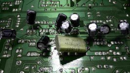
the first thing I moded was supply of the opamps from the section of filters.
I soldered the caps from the pins 4,8 and connected them to local central point of the ground.
I expected better trebles
but
got heavier bass and the sound was "more quiet" with "consistency"
I soldered the caps from the pins 4,8 and connected them to local central point of the ground.
I expected better trebles
but
got heavier bass and the sound was "more quiet" with "consistency"
Attachments
then
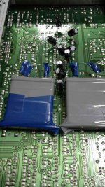
I shorted C99/100 and paralleled C93/94 with paper in oil caps 10u/160V.
like before expected nicer trebles
and
I heard beautifull voices the midrange is extraordinary!
wow, that was it
the conclusion is that smearing trebles is because weak quality opamps and they will be changed/ecluded with jfets during next mod.
I shorted C99/100 and paralleled C93/94 with paper in oil caps 10u/160V.
like before expected nicer trebles
and
I heard beautifull voices
the midrange is extraordinary!wow, that was it
the conclusion is that smearing trebles is because weak quality opamps and they will be changed/ecluded with jfets during next mod.
Attachments
Decoupling opamps isn't always straightforward.
If there is noise on the rails and you decouple to ground... then you inject that noise into the ground system. If that is used for signal purposes then you see the problem.
Sometimes just decoupling rail to rail can be best. It kills the noise and doesn't contaminate the grounds. I've also come to accept the view that a small cap and low value non inductive series resistor (say 2 ohm or thereabouts) can be the best compromise.
Decoupling opamps isn't always straightforward.
If there is noise on the rails and you decouple to ground... then you inject that noise into the ground system. If that is used for signal purposes then you see the problem.
Sometimes just decoupling rail to rail can be best. It kills the noise and doesn't contaminate the grounds. I've also come to accept the view that a small cap and low value non inductive series resistor (say 2 ohm or thereabouts) can be the best compromise.
anyway I decoupled rail to rail too, do you see a cap between the paper in oil caps?
but I will try to remove decouplers to the ground and check if the sound will be better?
because now is excellent
thank you for the comments
Decoupling modifications and especially with exotic parts can hardly be done afterwords IE the return to ground in such a complicated ( from design aspect) machine might have weird opposite or bad results .
Additions like the ones that you are trying to perform can be done either on a design stage or in equipment that is far less complicated inside . Use of exotic and often microphonic parts has way to many variables and there is a chance that will have worst results .Often one smd ceramic multilayer placed down under the OP amp will have better results than your approach ...you may as well try that.
It is very optimistic to think that op amps are drop in replaced Often OPAMPS with astronomical speed will require different compensation methods or circuits ( eventhough pins are compatible ) In cases like that oscillation is around the corner waiting for you .
Finally to be honest with you machines like the one shown eventhough from circuit aspect might perform many zeros when it comes to THD estimations but in real life the PCB and the structure of the machine will compromise and consume most of these zeros and make your mods worthless and most of all not cost effective .
That of course mainly applies to amplifiers ...audio section of tuners will be easier still the same rules apply ...
kind regards
sakis
 Hi
HiI resigned from this way of decoupling presented at the pictures.
I just decoupled almost every opamp from + to - with 100u/50V good quality cap.
I have make it for some HF IF chips too.
the same of the biggest caps from power supply section.
I paralleled output caps with WIMAs.
The results are outstanding, the sound quality is like from CDs >2000$.
Thank you for your advices
- Status
- This old topic is closed. If you want to reopen this topic, contact a moderator using the "Report Post" button.
- Home
- Source & Line
- Analogue Source
- Kenwood KT-1100