Hello,
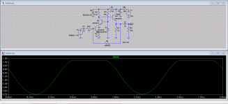
I have made my best too guess passive components values but it is far from being good enough. I am observing saturation phenomenon on positive side. Zener diode, labelled as D2, cut off voltage above 12V. Is my input stage that wrong or I will just need to adjust input stage parameter value ?
Best regards,
MaxS
Attachments
I have not been able to edit previous message.
First stage, made of Q1 and Q2 transistors, is a cascode stage where voltage gain is made. Second stage, made of Q3 transistor, is an emitter follower where current gain is achieved. Global performance of amplifier is dependant on a well designed voltage gain stage.
Right rail voltage is 15V, left rail voltage is 13.5V. Vz2, Zener voltage of D2 is assumed to be 13.5V. Voltage drop across R1 depends on Q1 collector current which depend on cascode design.
Any tips gentlemen ?
Hi Max,
You are posting on an ancient thread, long dead. Why not begin a new thread?
Have you built this, or are you just simulating it? If you are just simulating the circuit, try changing the values. That is super easy for you to do and isn't worth a question until you have banged away at it yourself. You can learn a lot from experimenting. Keep in mind that most people grew up having to build a circuit to see if it would work, or sitting there with a calculator (or slide rule) to find out.
We lock posts after a short while to keep everyone honest. That's why you couldn't edit your post.
=Chris
- Status
- This old topic is closed. If you want to reopen this topic, contact a moderator using the "Report Post" button.