I recently bought a Rogers Panthera tuner which has a deemphasis of 50uS. The deemphasis circuit is encapsulated in a module so I can’t reach the parts inside this module.
Can I build a RC circuit inserted in the output section so I can have a 75 uS deemphasis.
Do I have to add a 75uS deemphasis with R and C or a 25uS deemphasis because I already have a 50uS deemphasis in the tuner ?
Thanks a lot.
Can I build a RC circuit inserted in the output section so I can have a 75 uS deemphasis.
Do I have to add a 75uS deemphasis with R and C or a 25uS deemphasis because I already have a 50uS deemphasis in the tuner ?
Thanks a lot.
Your 50uS filter is a 1st order filter ( I assume). Adding another filter in series will increase the ultimate response to a 2nd order slope. The Q of the filter will be another problem.
To change to a 75uS filter you have to get the signal before the 50uS filter and possibly you need to remove the 50uS filter as it will also be loading the circuit.
Do you have a circuit diagram ?
Why would they encapsulate a 50uS filter ?
A simple 50uS filter is just a R and C combination.
L and C if it's 2nd order.
Are you sure what is inside the module ?
Cheers.
ashok said:Your 50uS filter is a 1st order filter ( I assume). Adding another filter in series will increase the ultimate response to a 2nd order slope. The Q of the filter will be another problem.
To change to a 75uS filter you have to get the signal before the 50uS filter and possibly you need to remove the 50uS filter as it will also be loading the circuit.
Do you have a circuit diagram ?
Why would they encapsulate a 50uS filter ?
A simple 50uS filter is just a R and C combination.
L and C if it's 2nd order.
Are you sure what is inside the module ?
Cheers.
Unfortunatly, I can't get any schematic diagram for this tuner
I looked at the circuit after the MPX chip and there's this module with two output transistors.
Last night I opened the module and there's 4 chokes which can be adjusted (variable) and 6 little capacitors.
For me, this means a lot of trouble to change something. This appears more complicated than a simple R C filter.
That encapsulated LC filter is the multiplex (MPX) filter, to avoid 38 kHz interference with the bias oscillator at tape recording. The deemphasis is usually a parallel RC complex at the stereo decoder chip. What is the type of the stereo decoder chip? The datasheet should show which pins are the deemphasis RC components connected to.
oshifis said:That encapsulated LC filter is the multiplex (MPX) filter, to avoid 38 kHz interference with the bias oscillator at tape recording. The deemphasis is usually a parallel RC complex at the stereo decoder chip. What is the type of the stereo decoder chip? The datasheet should show which pins are the deemphasis RC components connected to.
As I will never have a tape recorder in my system should it be a great idea to get rid of this LC filter ?
Thanks
De Emphasis
Hey:
To my lousy memory the only difference that you will hear is a lower level of high frequency response.
I think that if you leave the de emph. alone you will never know the difference except that you MAY have to reduce the treble a bit. Now if you are older like me the increased treble sounds good.
Hope this helps
Ed
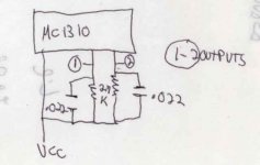
I finally found the R and C which make the deemphasis
There's a 2.7K and a .022 uf cap for each channel as seen in the drawing.
In the National typical application sheet, they show a 3.9K and a .022 uF. I tried a 3.9K instead of the 2.7k and I think that the sound is perharps worse with more or as much treble than it was.
Can someone help me
Thanks
There's a 2.7K and a .022 uf cap for each channel as seen in the drawing.
In the National typical application sheet, they show a 3.9K and a .022 uF. I tried a 3.9K instead of the 2.7k and I think that the sound is perharps worse with more or as much treble than it was.
Can someone help me
Thanks
Attachments
Hi,
your 50uS de-emphasis raises the treble into a shallow shelf response from about 2100Hz upwards of about 1 to 2db.
If you don't like this treble emphasis then a downwards shelving response could correct for your 75uS pre-emphasis signal.
It's a bit like the way RIAA works with a shelf response. The correction will not be that accurate but better than the existing.
But, these experts should be able to identify the correct components.
BTW,
that diagram of pins1&2 was not the de-emphasis.
Hi.
I do not wish to change the subject, but I recently bought a Rogers T75 mk2 tuner and am having problems with the output voltage.
I know that the DIN standard is lower than phono, but what I am getting is close to the output of a moving magnet cartridge.
What I am really after is a schematic or service diagram so that I can maybe sort it out, and the only information I can get is on this posting.
I would appreciate any help you can give.
Sorry to jump in like this.
Hi again.
Just thought I would update my request, it turns out that the output was fine and that the DIN connector was wired to the left of earth instead oif the right, so all I was getting was a bit of bleed.
I felt a bit stupid, but sometimes the simple things are overlooked.
Cheers anyway.
Just thought I would update my request, it turns out that the output was fine and that the DIN connector was wired to the left of earth instead oif the right, so all I was getting was a bit of bleed.
I felt a bit stupid, but sometimes the simple things are overlooked.
Cheers anyway.
- Status
- This old topic is closed. If you want to reopen this topic, contact a moderator using the "Report Post" button.
- Home
- Source & Line
- Analogue Source
- Changing a deemphasis from 50 uS to 75 uS