Hi,
I was going to replace the motor and managed, but unfortunately I made a few mistakes and shorted the PCB due to small copper threads stuck on the PCB. I should have been more careful cleaning it. Nevertheless I am in the process of desoldering and trouble-shooting. Found that the D2/D3 and C6 were dead (see also image). Also C3/C5 measured strange. C1/C2 ok, as C8/C9. Remaining electrolytic caps seemed fine. R2/R3 and D1 measures fine.
I suspect however that some of the ICs might have failed. Any way to measure them with a DMM to check? I suspect U1/U2. How about U4 (LM324).
(I did a switch of the pulley to another motor, but it is still not centered, so I'l try with the LP12 motor with pulley installed.)
Yes I know. Motor is changed for other reasons. Skewed axis. The unit worked fine otherwise. Most electrolytics measured fine as I wrote, the error came after a short due to my mistake not cleaning the board. So this is not the usual electrolytic cap error.It's almost never the motor. Always the electrolytics. Change all of them.
Last edited:
It certainly looks a bit worn but measures fine. It looked like that when the unit worked fine as well.R3 is ******. Change the high power resistors
Best to change the resistors regardless of how they measure. R3 has certainly been overheated. Are you measuring the caps in circuit? This won't give you proper readings as some of them are paralleled. Either way, regardless of how they measure, all of the electrolytic caps should be replaced. They're not expensive and those ones in there are at least 25 years old.
The Axis boards is a rather fragile thing and traces are easily damaged when removing components. It's very easy to pull the pass throughs from the component holes that connect the traces from the lower and upper side of the board.
The ICs in my experience are pretty robust and I've never had to change any. Which part of the board shorted and do you have the circuit schematic?
Agree that R3 is "on its way". Traces are ok so far. One part which was damaged was the D2/D3 diodes; they were split in half (se picture). C6 was gone as well. R10 looked as if had a "choke" as well but it measures ok. The closest IC is U1 and U4 connected to diodes, which I suspect may have been damaged.
The record player initially played after the motor change, but did not come up to speed. Checked and it turned on directly (red diode on) when plugged in, but no function. Found out there were some shorts but difficult to say if there are more than what I've observed.
The caps have been measured outside the PCB and all were fine except for C6 and C3/C5. The C1/C2 measured 46 uF. Q1/Q2 fine as well.
Will replace caps except for C8/C9, D2/D3, U1 and U4. Then well see. Will install an LP12 motor with its pulley.
The board is up and running BUT the motor of the Axis is different from the Premotec 9904 111 31818 110V 50 Hz motor. It is also different from the LP12 9904 111 31819 motor. Windings read 4.45 kOhm of these motors, while the Axis motor, Airpax 9904 111 31818, reads 2.45 kOhm.
Sadly I think there is no replacement for the Axis motor around, so I'll have to return to the Airpax. I will try mounting the LP12 pulley to the old motor.
Sadly I think there is no replacement for the Axis motor around, so I'll have to return to the Airpax. I will try mounting the LP12 pulley to the old motor.
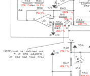
If you alter the values of R50 (33.33 rpm) and/or R51 (45 rpm), the 'motor run' voltage will change.I wonder if someone could help with modifying the control so that the operational voltage would be 45V rather than 25V? It could probably solve the operation of the new motors with higher winding resistance.
If you remove R50 and/or R51, the 'motor run' voltage will always be maximum.
Good Luck experimenting...!

Thanks!If you alter the values of R50 (33.33 rpm) and/or R51 (45 rpm), the 'motor run' voltage will change.
If you remove R50 and/or R51, the 'motor run' voltage will always be maximum.
View attachment 1156344
Good Luck experimenting...!
Running into problems, and I don't know what else to check.
I got it to play last weekend, the day after something wrong. Have changed the usual electrolytic capacitors, the U1, U2, U4 ICs on sockets now. When I plug in the cord I see the usual faint red diode light, which goes out (as it usually does), but when I set click it on, there is no red diode light, no motor running. Checked the switch, it is ok as well. Diodes ok. There is 13.8 V on the U1 and U2 coming through. I could keep changing ICs but without knowing I would like to get some hints where to look. Could 4066 errors cause this (i.e. no red diode light when turned on)?
I got it to play last weekend, the day after something wrong. Have changed the usual electrolytic capacitors, the U1, U2, U4 ICs on sockets now. When I plug in the cord I see the usual faint red diode light, which goes out (as it usually does), but when I set click it on, there is no red diode light, no motor running. Checked the switch, it is ok as well. Diodes ok. There is 13.8 V on the U1 and U2 coming through. I could keep changing ICs but without knowing I would like to get some hints where to look. Could 4066 errors cause this (i.e. no red diode light when turned on)?
Last edited:
I am almost done now, found a short in one of the sockets and also that one of the 33 uF capacitor had died. The motor spins not but the 33 RPM starts at around 81-85 volts, drops suddenly to the usual 25V but jumps up again to 80 V. So the motor does not stop as it used to. The 45 RPM works as it should, it drops an stops the motor. Have changed all ICs except for the U3/U5 but I can't see from the schematics that these would affect. It's seems like a switch that goes back but only at 33 RPM. Anyone have an idea what the issue can be?
(BTW Changing the R50 to 30K makes the drive voltage at 45V, which I am aiming for with the LP12 motor. Will check the 45 RPM as well/R51 to get about the same)
(BTW Changing the R50 to 30K makes the drive voltage at 45V, which I am aiming for with the LP12 motor. Will check the 45 RPM as well/R51 to get about the same)
I have adjusted the values further, R50 to 30k - giving a voltage of around 45 V. The load sensing does not work though, and it could be short in U7. But I also wonder if the motor restistor R14 (10 ohm) needs to be adjusted to the new motor, since winding R is higher? I got a bit more stable pulley and lower 4.16 Hz wow with the new motor, but also gained 50 Hz noise.
Old motor vs new motor:


Old motor vs new motor:
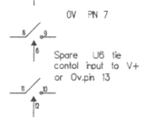
I still have not managed to get it "back in track", even if it works at high voltage when stable. I can set resistors at R50/R51 to lower the voltage, but it is intermittently unstable, with fluctuating drive voltage. I have checked what I can, and I have only two suspicions. Either it is the motor resistor that need change or there is something going on with the U6 or U7 switching. Does anyone know what the "NOTE means for the U6 chip?
Attachments
- Home
- Source & Line
- Analogue Source
- Repairing Linn Axis Motor Drive Amplifier