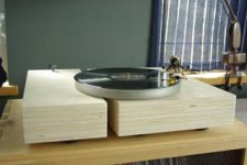
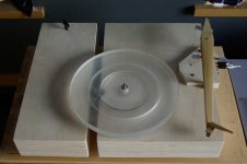
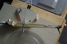
side view. 7 layers of birch plywood glued and screwed together. The central support is tied to the 3rd plank from the bottom, then sandwiched between the others. The motor assembly is attached to the left half. Getting the height of the motor was a pain. The acrylic platter has a very small margin for it, to low and the rubber band comes off, too high and it hits the bottom of the platter. Adjustable feet would have been nice, but I went with the aq soft rubber feet.
Attachments
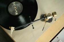
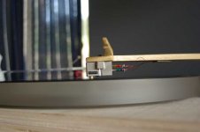
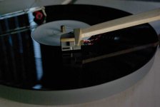
The tonearm. I made the headshell from plywood. The cartridge is glued to the headshell which is glued to the arm for the best contact. They are throw away, when I pick another cartridge I'll make a new one. The wire is pure silver and continuous to the RCA plugs.
Attachments
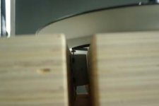
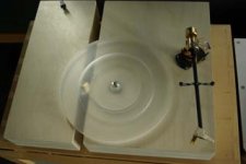
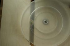
A close up of the acrylic platter, with the underneath cutoff for the rubber band and motor.
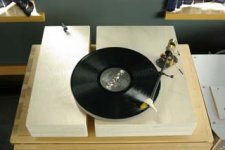
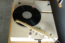
The final sound is much tighter than before, with much better bass, and the vibrations are well taken care of by the rubber feet and the weight of the assembly. It is also much less prone to jumping as a result of somebody walking by since the springs are gone.
The final sound is much tighter than before, with much better bass, and the vibrations are well taken care of by the rubber feet and the weight of the assembly. It is also much less prone to jumping as a result of somebody walking by since the springs are gone.
Attachments

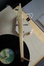
Alright, finally finished phase 2 of the modifications: the tonearm.
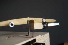
It is made of poplar, a light wood. The bearing is unipivot with 2 elements: on the arm I cut off an alan screw head that came to a point. On the table end it is one of those punch screw drivers with the handle removed. Both were picked for the hardness and sharpness qualities.
The arm's pivot point is as high as possible, and the center of gravity as low as possible, with various screws and elongated nuts to balance both on the length and width.
Attachments
Details of the pivot and counterweight. Really pretty simple. Just make sure the hole is drilled vertically.
There is a long wide screw with all those washers that can screw in an and out for fine adjustments (or you can add washers for coarse adjustment). It goes into a nut that is hammered and glued to the block of wood.
There is a long wide screw with all those washers that can screw in an and out for fine adjustments (or you can add washers for coarse adjustment). It goes into a nut that is hammered and glued to the block of wood.
Attachments
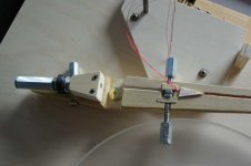
The bottom view. The side adjustment screws (for adjusting the cartridge horizontally) are carved and glued into the wood so that their threads are sticking out on either side. By turning the large nuts in and out you can level the arm horizontally.
The screw in the back compensates for the cartridge and holder's weight.
The wiring is pure silver and glued in. The triangular woodcuts make sure they stay put.
The screw in the back compensates for the cartridge and holder's weight.
The wiring is pure silver and glued in. The triangular woodcuts make sure they stay put.
Attachments
- Status
- This old topic is closed. If you want to reopen this topic, contact a moderator using the "Report Post" button.
- Home
- Source & Line
- Analogue Source
- pink triangle mod