Hello friends,
I obtain the PSPICE simulation of a simple LCR parallel circuit, and formed some doubts regarding it.
The voltage response across the LCR circuit at resonant frequency turned out to be dissimilar when i changed the L/C ratio.
In such a tuned circuit it shouldnt have happenend if PSPICE considers L and C elements as ideal , with no internal resistances.
I have posted the simulation results and the schematic of my tiny expperiment.
Kindly post the answers that you guys have.
Regards,
Prasanna Rao.
Attachments
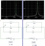
LCR At resonance
Ok, thanks for that info.
Forgive me with ideas, if i am wrong over here.. As far as i know, the Q factor of a tank circuit would affect its response at frequencies other than the resonant. At resonance, -jXc = jXl, so the impedance of the circuit would be purely resistive (1k in our case).
In short, if i maintain the same LC ratio, the response at RESONANT frequency should be the same.
Regards Prasanna..
It's all goodForgive me with ideas, if i am wrong over here..
")
The response at the resonant frequency will increase with Q, the curve will also be more sharp.
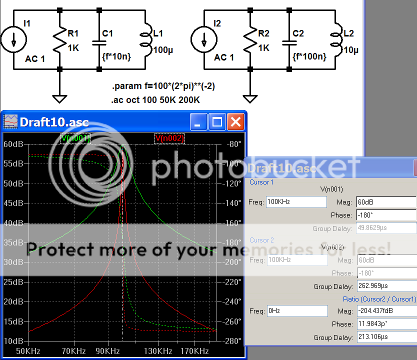
BTW, both of your curves are fairly high Q. Experiment with 1mH/1nF and 10mH/100pF.
I do agree with your 2nd statement regarding the curves. Everything is ok with the Q factor of the ckt, as it depends on the L/C ratio and R.
But you say :
I am afraid I cant understand that. To make it more confusing, the results in my experiment were exactly opposite. I have posted its frequency response in the first thread of this topic.
At resonance here's what must happen :
The impedance seen across the ideal LC parallel section is infinite. Now if I increase C and decrease L; or do it vice-versa such that the L*C product remains the same; then it should still offer me with infinite impedance at that very same resonant frequency.
So, at resonance the net current in LCR ckt is only due to R (since Z = R). Then Itot*R = Vresponse, must be the same even if i change the L/C ratio.
Huh.. God help..!
Regards Prasanna.
__________________
But you say :
The response at the resonant frequency will increase with Q
I am afraid I cant understand that. To make it more confusing, the results in my experiment were exactly opposite. I have posted its frequency response in the first thread of this topic.
At resonance here's what must happen :
The impedance seen across the ideal LC parallel section is infinite. Now if I increase C and decrease L; or do it vice-versa such that the L*C product remains the same; then it should still offer me with infinite impedance at that very same resonant frequency.
So, at resonance the net current in LCR ckt is only due to R (since Z = R). Then Itot*R = Vresponse, must be the same even if i change the L/C ratio.
Huh.. God help..!
Regards Prasanna.
__________________
OK. I've checked this so it should be correct. 
A tank circuit is a parallel capacitance and inductance. The Q of the tank circuit on its own should be infinite. In practice it is not. The inductors winding resistance damps the Q. The formula for the Q of the tank alone is: Qtank=XL / Rwinding.
In your circuit the tank is loaded by resistance. The resistance is the parallel combination of the 1k resistor and the source impedance. This is because the source is a short circuit to AC save for its own impedance. Since you are using a current source (infinite impedance), we need only consider the 1k.
To calculate the circuit Q, first calculate Ztank.
This is XL^2 / Rwinding and since we have no winding resistance this is infinite. Then we need to put this in parallel with the load resistance. So in total we have 1k.
We then divide this by XL. If the resonant frequency is 159,155Hz , then XL=10 ohms for the first circuit. The Q is then 100.
When the Q of this type of circuit is reduced, the bandwidth is increased, and vice-versa.
Hopefully, this clears the air a little and answers your question
BTW Jan, sorry for the overpost.
Hello Sir ,
Yes everything is right in its place. But the mystery about different voltages at the same resonant frequency remains..!
Q must not alter the o/p voltage at resonance. Infact that's what we all have shown in some way or the other, in our respective posts.
I have asked this doubt to some of my coll. buddies and they too accept the same question mark.
One test would be to do it *without* the R and see what the difference is in the two cases.
I suspect that the sim has a hidden R // C to satisfy DC conditions, most Spice simulators have.
Without R, the Q remains around 55 in both the case. Even with R = 1K, the observed Q in case A is 54, whereas theorotically it comes out to be 10000..!!
Surely PSPICE might be considering coil resistance and/or other parasites of L and C. But then no such attributes are defined in their models..?
If someone knows the answer please reply.
Regards, Prasanna Rao..
____________________
xitronics said:
Even with R = 1K, the observed Q in case A is 54, whereas theorotically it comes out to be 10000..!!
Oh a mistake by my calci
 , therotical value of Q with R = 1K is 100. Anyways, its still deviant.
______________
Prasanna Rao.
you might need to dig into spice settings that control the accuracy and defaults of the simulation, in LtSpice a default R damps inductors without explicit Rser declarations, you have to turn it off in the control panel
in .ac sim you need to use a very fine frequency grid to hit the 1/(2*pi) * 10e6 resonance exactly, or change component values to match a even frequency
with LtSpice I get ~ 1% amplitude difference even with 10000 points/oct freq resolution
in .ac sim you need to use a very fine frequency grid to hit the 1/(2*pi) * 10e6 resonance exactly, or change component values to match a even frequency
with LtSpice I get ~ 1% amplitude difference even with 10000 points/oct freq resolution
jcx said:
you might need to dig into spice settings that control the accuracy and defaults of the simulation.
That's right. But i havent found any data in the model of L in PSPICE; which represents its series DC resistance. Surely, Rseries is the only reason for the non-ideal voltage response in my experiment.
I am trying to go deep into PSPICE and seek that Rseries data for L. If anyone knows regarding it then kindly present them in this thread.
Regards Prasanna.
_______________
Now problem in Transient Analysis
Oh great..! The problem for AC sweep is solved. I increased the points/octave value to 10000 and the response is almost perfect.
But the transient reponse is absurd. Its showing amplitude of Vr = 10V at resonance, where should actually be 100V. Whats this problem for..?
I have attached the transient response with this post.
Kindly reply if anyone has any answer.
_________________
Regards Prasanna.
Attachments
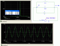
Just a thought, your time stepping seems a little coarse.
Didnt get it..
.. Could you pls elaborate more on that..Regds Prasanna
_________
- Status
- This old topic is closed. If you want to reopen this topic, contact a moderator using the "Report Post" button.
- Home
- Source & Line
- Analog Line Level
- Loaded Tank circuit lossess -- PSPICE Simulation