Yes, and I use the NSL32SR2S which go lower in impedance and also stay lower (5X less) in max impedance than the NSL32SR3. Maybe that's the "mushy" or maybe it's the way they're being powered
And I also quad match them between 1-20mA which also gives a far better log feel to the volume rotation and never in hundreds out there has anyone said "mushy" at min attenuation. Even with super efficient horn systems that are almost at 8pm for normal level. I think there "mush" somewhere else, and it's not in the Lightspeed if you know what I mean.
Cheers George
When I talk about 6k I mean when you set the max resistance of the series or shunt LDRs I like them at 6k.
Andrew, yes folks have had preferences for different max resistances in shunt and series. Obviously its subjective and right back to similar arguments about the sound of tubes or transistors. I cant say they preferred one setting over another because I never took a poll or kept track. I like 6k best in my system and I do hear a difference in the way I described between 6k and, for instance, 22k.
Any of you can try it. Increase the max resistance of both series and shunt and see if the sound doesnt get more tubey, soft, etc. Then decrease it and see if it doesnt get more transparent and hyper detailed. I like it in the latter form best but its subjective, obviously. Its not a big deal, I just like 6k better in my system which has a source output impedance under 100R and an amp input impedance of 22k (I used to think it was 47k but when I rebuilt my amp a few weeks ago I found it was 22k). If you want to try messing with the max resistance and you are using a Lightspeed then you can simply place a 100R multiturn trimmer in series with the output of the regulator and the input of the 100k pot. Turn it in the 0-10R range and you will make huge differences in the max resistance and you can even listen while you turn the trimmer.
George did I shoot an arrow across your bow? Did I slam your Lightspeed or am I here on this thread because I think its a great idea? Get over it man.
Wapo I cant definitively answer your question about how much wavering is okay as time would also play an important part in that answer. Is wavering every second by 50R okay or wouldnt wavering by 50R over 10 seconds be better? I would suggest that 50R would be fine even if it changed back and forth 50R every few seconds. We would not be able to tell at 10k. Even if series and shunt were both at 10k and shunt wavered by 1k the difference is only about .4db so we would probably only notice that if we were really paying attention. Wavering matters but not a lot. Some LDRs waver less than others at the same resistance. I would prefer an LDR that does not waver as I would assume it is simply a more reliable device.
I'm curious to know how that circuit performs. May I ask -- what resistance range does your "pot" cover, and at what supply voltage?
What is the resistance stability at the high end of the range? I'm curious to know how much the resistance wanders at, say, 10K. I have found that this measurement -- resistance wander at 10K -- is probably the most accurate way to judge the effectiveness of a control circuit.
I have been satisfied with a range of +/- 100 ohms at 10K which is 2% and that's good, but I think it's possible to do better, maybe 1%. Current wise, +/- 100 ohms at 10K constitutes a current variation of about +/- .002ma around a base value of .010ma.
I don't have the circuit in front of me, But I use typical pot values of 10k to 100k, and supply voltages of about 5V. With this scheme, you can vary the supply voltage (downward) for more low end range. I use a FET instead of the bipolar shown in the app note, and also use precision single supply op-amps that have low offset and are specified rail to rail to make things simple on the power supply (no need for +/-). These are not the typical audio approved op-amps folks use.
The other nice thing is the "sense" resistor can be variable to give the user some front panel balance capability. But the pot must be able to take whatever current you are sending through it. I have spare wire wound ones here, so they work fine, sorta overkill.
I've found the stability to be overwhelmingly temperature and current dependent. I actually match LDR units in winter at a constant 68F ambient and measure that local ambient temp to 1 degree with a 4 1/2 digit voltmeter / precision thermistor. Otherwise, I can't match with repeat-ability.
The current through them will also self heat them, and when decreasing current from large values they need long recovery / settle time to go to the true value. This is not a problem, as long as they all behave more or less the same, and settle about the same. Thermal mounting with a common environment will likely help if you are picky on this part (wax, common heat sink, etc). So if you measure a singular unit at 10K, I think most of the wander will be temperature related, not control circuit related. Touch the LDR with your finger for for 3 seconds while doing the wander test, and watch the results.
The op-amp feedback circuit with current sense resistor and FET current gating works extremely well, no problems with stability there, provided you use the correct parts as above. It's easy to build too, if you are used to that sort of thing.
But, as in all things, this is my way of doing it, I'm not saying the figure 5 circuit is the best, or what anyone else *should* do. It's what you can do, and works well, if you are interested in playing around with it.
Wapo I cant definitively answer your question about how much wavering is okay as time would also play an important part in that answer. Is wavering every second by 50R okay or wouldnt wavering by 50R over 10 seconds be better? I would suggest that 50R would be fine even if it changed back and forth 50R every few seconds. We would not be able to tell at 10k. Even if series and shunt were both at 10k and shunt wavered by 1k the difference is only about .4db so we would probably only notice that if we were really paying attention. Wavering matters but not a lot. Some LDRs waver less than others at the same resistance. I would prefer an LDR that does not waver as I would assume it is simply a more reliable device.
Good point about the time aspect of resistance waver. As I watch my system at 10K, it seems to mostly stay well within +/- 50, and then occasionally swings out to +/- 100R so I guess that's OK. I didn't know that different LDRs would act differently in that respect, I thought it was minute variations in the current that was causing it. Also my understanding is that in a potentiometer the lower resistance always plays the dominant role, so variations in the higher resistances won't be noticeable when paired with a low resistance on the other side of the pot.
A side benefit of my calibration process is that I can program entirely different maximum resistance values for R1 and R2, so it's possible to program R1 to go from 50R to 6K, and R2 to go from 50R to 12K, for example. The intent is to allow for a wide range of system efficiency, but I think that would also give you the benefit of a low Z pot while allowing greater maximum attenuation. Not sure what the attenuation curve will feel like if you do that -- whether a smooth log or something less comfortable.
A side benefit of my calibration process is that I can program entirely different maximum resistance values for R1 and R2, so it's possible to program R1 to go from 50R to 6K, and R2 to go from 50R to 12K, for example. The intent is to allow for a wide range of system efficiency, but I think that would also give you the benefit of a low Z pot while allowing greater maximum attenuation. Not sure what the attenuation curve will feel like if you do that -- whether a smooth log or something less comfortable.
Thats cool. Maybe if you had an odd looking curve you could just add more or less volume stops in the curve which would give it that log feel.
I have many times used the tactic you talk about.. using a higher max resistance on series than on shunt to help give folks with a super efficient system better use of their volume knob. If they complain they cant turn it past 9 then just adjust series and shunt and voila! Of course now they can never get something close to 100% volume but they never wanted that anyway.
EDIT: If you can easily adjust the number of volume stops then you would never have to do this series/shunt max resistance trick though. Just increase the number of stops.
EDIT2: Also wanted to respond to your comment about some LDRs wavering and some not.. I do mean that they are all still the same part number. I dont use the SR2S, God forbid, but I do use the SR2 and when you have a lot of them on the test jig at once you will notice that some are really stable and some waver quite a bit. Even more odd is that when most are hitting, lets say 7k, some will be hitting crazy numbers like 20-50k so I like your method of creating some sort of look up table because it makes using LDRs more economically efficient. I came up with the resistor replacer idea simply to get rid of a plethora of unused LDRs that wouldnt match any others. Try replacing resistors in your amp with an LDR. It really makes a difference and its an improvement.
Last edited:
I use typical pot values of 10k to 100k, and supply voltages of about 5V.
Those numbers are for the controlling pot, not the actual attenuator built from the series and shunt LDRs. For that it's values in the range everyone else uses on the low end, maybe a little higher (60-80 ohms). On the high end, it can be very high, as you can precisely control current to micro amps, to give very high resistance numbers, way over 10k.
Matching above this range is harder, of course. But it does allow a circuit that goes to zero sound output, versus is -5x or -6x dB. And whether you prefer no control whatsoever below say, -50 dB, or non-optimal balance withstill some volume control capability at say -70dB or -80dB, is up to you.
EDIT: If you can easily adjust the number of volume stops then you would never have to do this series/shunt max resistance trick though. Just increase the number of stops.
Actually, I've figured out a way to deliver continuously variable control with no steps. Now that I've got the control code working with good accuracy, stability and speed, the rest is just a matter of time.
Up until this morning I was limited to controlling the LDR by commanding a certain current and driving the LDR to that current, but I finally got the software working so I could command a resistance and drive the current to that resistance. Still kinda crude, but working, and this is the key to the calibration process.
Those numbers are for the controlling pot, not the actual attenuator built from the series and shunt LDRs. For that it's values in the range everyone else uses on the low end, maybe a little higher (60-80 ohms). On the high end, it can be very high, as you can precisely control current to micro amps, to give very high resistance numbers, way over 10k.
Matching above this range is harder, of course. But it does allow a circuit that goes to zero sound output, versus is -5x or -6x dB. And whether you prefer no control whatsoever below say, -50 dB, or non-optimal balance withstill some volume control capability at say -70dB or -80dB, is up to you.
I have controlled my LDRs up to about 100K a few times but haven't looked at that much because I did not see a need for it. The resistance did wander by a fair amount, I think it's safe to say generally that the wavering can be characterized as a percentage of the resistance. If my control is within 2% of target at 10K, probably it will be the same 2% at 100K, but hitting an absolute value at 100K is not easy because each microamp change has such an effect on the resistance; probably would need to be satisfied with +/- 10K or so, maybe twice that.
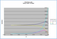
Since we've been talking about pots with different R1 and R2 values, I thought it might be interesting to see what it does to Zin and Zout. The attached image shows the relationship for a pot with R1= 5K and R2 = 15K. Source impedance = 100 ohms, Load impedance = 10K ohms.
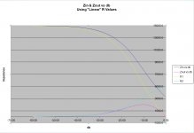
Oops. On the previous chart in #5191, I got the R values backwards. This is what it should look like (with R1 = 15K ohms and R2 = 5K ohms, 100R source, 10K load).
I have long been suspicious of the statement that LDRs change resistance when temperature changes. I have always believed that the change in LDR resistance was caused by a change in current passing through the LDR when the LED heated up, and the change in resistance was caused by an actual change of current.
Today I was running a current-controlled LDR at 10K resistance and my current regulation was keeping the resistance at 10K +/-15 ohms. On a whim I got an ice cube from the freezer and applied it to the LDR and held it there. The average resistance changed by a whopping 10 ohms. I believe the lack of change in resistance is because I was tightly controlling the current and when the LED got colder the regulation circuitry kept current unchanged and therefore resistance unchanged.
So, I think that in a current-controlled environment the LDRs are not as susceptible to temperature change as they are in a voltage-regulated environment.
Attachments
So, I think that in a current-controlled environment the LDRs are not as susceptible to temperature change as they are in a voltage-regulated environment.
and you are not trying to 'catch' customers here, are you

Lightspeed is what it is
I didn't feel like I was crossing a line in making a comment about an empirical observation about a subject (effect of temperature on LDRs) that frequently has been in the past and should always be of interest to anyone who uses LDRs under any circumstances, period.
However, I don't like to offend and I truly am tired of never knowing when something I say will offend someone on this thread, so this is my last post.
However, I don't like to offend and I truly am tired of never knowing when something I say will offend someone on this thread, so this is my last post.
I was feelin it, as were others that emailed me about it.
I have hundreds out there, and many more diy made from this thread not one with your findings, any returns I get are never related with this problem. But like car batteries being hooked up the wrong polarity and general mains related blow ups, and bench testing with many volts input and shorted outputs, taking out the ldr's.
As for the temp of the ldr's this is why I've always advocated never to be put in amps or preamps where the temp can vary double even tripple, to be use in their own chassis with external transformer pack, as the production Lightspeed Attenuator is made, and for good measure to pot all 4 matched ldr's together in hard wax.
And you do have your own LDR thread, why not use it to post these questionable findings there? http://www.diyaudio.com/forums/analog-line-level/170381-precision-led-ldr-based-attenuator.html I'm with tinitus, I smell a spruik in the air.
Cheers George
 )
)Today I was running a current-controlled LDR at 10K resistance and my current regulation was keeping the resistance at 10K +/-15 ohms. On a whim I got an ice cube from the freezer and applied it to the LDR and held it there. The average resistance changed by a whopping 10 ohms.
1000 ppm versus 20°C change (room temp -> 0°C) gives 50 ppm/°C
same as the 1% MELF resistors seen everywhere here...
To get 50 ppm/°C drift on the current source feeding the LED needs some design effort ...
Not to mention the current to light conversion of the LED versus temperature...
IMO it's really, really good for a LDR to get 50 ppm/°C considering it's not really a vital parameter...
(PS : the copper in your voice coils has 4000 ppm/°C tempco)
Tinitus and George et al:
Having been on the receiving end of a personal attack based on total lack of knowledge of my situation and intentions, I’m taking this one last opportunity to respond – simply to clear up misunderstanding which I believe there is plenty of.
I am not a competitor to George attempting to steal potential customers. I am pushing seventy years of age and have enjoyed full careers as a military pilot and air traffic controller and manager of ATC organizations and I have never been in business. Whatever funding I need for retirement, I have already made and I don’t need to compete with anyone, least of all in a field which I view entirely as a hobby and a fascination.
George’s customers are counted from those who love an elegant simple design that delivers exceptional sound. They don’t need me. My design (should it ever actually come to pass) is high-tech, complicated, and would be far more expensive to implement. George’s customers and my customers would come from different pools, don’t you think? Assuming I ever have a product and ever have a customer?
Of course, that assumes I’ll ever have a single customer and that’s questionable. This is my hobby and my fascination, not my vocation. I have zero training in electronics or audio or computers or running a business and I don’t pretend to be an expert in anything. I am a retired pilot with a fascination with electronics and audio and a curious mind, that’s it. The one thing I bring to the table is the combination of interests – digital programming and audio processing. Maybe that’s worth something.
Frankly, LDRs are screaming for attention and they caught my interest because there is so much word-of-mouth nonsense and so very little science-based fact being dealt with here, no wonder there is little progress in adapting their application. Well, that runs counter to my frame of mind – I need to know facts, to separate “he said” from “he proved.” But frankly, it’s lonely out here – there is no one for me to talk to who seems willing to share knowledge and the burden of moving the science of LDR usage forward. So, I come to this thread in search of someone to talk to who knows something about the subject. In the past, useful discussions have happened but now I see they were not with George’s blessing – he was gritting his teeth. I’m sorry to have been part of your frustration, George, I never intended that. Henceforth, I will publish “in the blind” in the Precision LDR thread. Thanks for listening.
... I am pushing seventy years of age and have enjoyed full careers as a military pilot and air traffic controller and manager of ATC organizations and I have never been in business. ...
Off topic but:
What airframe?
I am pushing seventy years of age ...
wow ... cool

Lightspeed is not going to change
but your 'special subject' may deserve its own thread
The Lightspeed method basically removes contacts from the signal path. I have two different LDR applications that begs to be assembled and tested, an I should be doing this in the near future. Other than lack of physical contacts, I think there are other qualities that I expect to see in measurements. Look forward to doing that.
- Home
- Source & Line
- Analog Line Level
- Lightspeed Attenuator a new passive preamp