Rudi, I am looking at your photograph and the MCP602x datasheet. I guess the 8 pin DIP in the upper right corner is your 6021, but I can't visualize the function of a single op-amp in a circuit where there are two pot sections and four legs to be controlled. If the purpose was to offload managing the current from the pot onto the op-amp, I would think you'd use a 6022 or 6024 with two or four amps, so that can't be it. Could you tell me what that single op-amp does, please?
It serves as a buffer for the voltage across one of the LDR's LED in order to measure actual volume attenuation. Its output is connected to ADC input of the PIC.
Last edited:
It serves as a buffer for the voltage across one of the LDR's LED in order to measure actual volume attenuation. Its output is connected to ADC input of the PIC.
Thank you for that enlightenment. I thought it was part of the current control circuit.
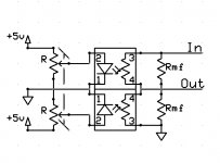
George, I'd like to ask your opinion about using metal-film resistors at the output of an LDR potentiometer as pictured.
I understand that they will affect the response curve of the pot; however, I'm mainly interested to know if you believe that they would adversely affect the sound of the LDR pair. What do you think?
I understand that they will affect the response curve of the pot; however, I'm mainly interested to know if you believe that they would adversely affect the sound of the LDR pair. What do you think?
Attachments
George, I'd like to ask your opinion about using metal-film resistors at the output of an LDR potentiometer as pictured.
I understand that they will affect the response curve of the pot; however, I'm mainly interested to know if you believe that they would adversely affect the sound of the LDR pair. What do you think?
Not only the respones curve but also the min volume achievable, and the nice log feel to the progression of the level control, this is why it is as I have found always better to quad match all the LDR's and not try to short cut with buffering ressitors.
As for the sound of resistors, some think they all sound different when in circuit, and some believe that the unique sound of the Lightspeed is due to the composition of the LDR itself, as well as no contacts in the signal path.
I cannot see why not as the Lightspeed is powered after the toroidal with it's own 5v regulated power supply, so long as there is no sag in the the toroidals voltage it should be fine to power both from it.hi guys, I'm building my new f5 with lightspeed and speaker protector by diyaudio. Can you tell me if I can use a single toroidal 12v to power these two circuits?
Just be careful that there is no temp swings inside the F5 if you plan on putting it inside it that the Lightspeed circuit will see, or you will get channel imbalance drift.
Cheers George
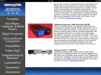
Lightspeed Attenuators owners and diyer's, I've just been informed again by Stereophile, and you'll be happy to know that your Lightspeed has just made it again into the Recommended Components with the highest 3 x $$$ rating for sound and value for money in the next issue.
You can download it free via Apple Ipod from the Stereophile website or wait for the hard copy to come out.
Cheers George
You can download it free via Apple Ipod from the Stereophile website or wait for the hard copy to come out.
Cheers George
I downloaded the app, but not sure what to make of it. Have not found the light speed on it.
Someone who downloaded the app sent this to me, as I don't do Apple myself.
Cheers George
Attachments
It serves as a buffer for the voltage across one of the LDR's LED in order to measure actual volume attenuation. Its output is connected to ADC input of the PIC.
That would measure the commanded attenuation, not the actual attenuation.
Actually, it would only measure the commanded resistance of only one of the LDRs (photocell), if you only measured across one LED.
To measure the actual attenuation, you would need to measure the voltages across BOTH of the photocells (i.e. the LDRs, not the LEDs), and then do some arithmetic involving the two measurements; at least one ADD and one DIVIDE, I think.
Even the layout of the app looks different.Someone who downloaded the app sent this to me, as I don't do Apple myself.
Cheers George
Even the layout of the app looks different.
Its a Screenshot of the Stereophile Recommended Components 2013 App. You can get it at the App Store free.
Cheers
'Nutz
Guys..I have a question about the Lightspeed Attenuator.
What would cause the volume control to become inoperative ??
Here`s a little background to this question.
Seems a gentleman had a problem with his Lightspeed, apparently it had a channel imbalance and he sent it back to George for repair .
According to him, George put a new set of LDRs and fixed the imbalance issue.
He said it worked fine for a few weeks then last Monday it got way too loud with the volume knob having no effect at all.
Seems it`s FULL volume ALL the time.
Not wanting to send it all the way back to George again, he decided to sell it.
I`m awaiting its arrival in a couple of days and am needing some ideas on what I might look for or do to hopefully fix it.
Any ideas ??
So would it need another whole new set of 4 LDR`s.
The seller stated that it cost him a little over $200.00 !
I certainly hope I don`t need to go that route.
I understand this is a DIY Forum but I really am a complete know nothing and I don`t know what is meant by your statement...sorry.
I do appreciate any and all help though, so I`ll try and learn enough to get me through this.
Thanks
Steve
Start by measuring all the voltages into the LDR. If there is no voltage going to the shunt ldr, they will be at 1Mohm and you'd have a very little attenuation regardless of what is going on with the series ldr. If both channels are loud, sounds more likely power not going to that half the circuit than both ldrs being blown. Could just be a single broken wire or a bad solder joint. Likely cost you nothing. If you paid very little you are likely to get a great deal. If the ldrs are dead then yes you need to replace them all. Still not a big deal.
Check the signal ground wires for loose connection or broken. I fixed a lightspeed for a guy and the signal ground wire had come loose. I bet its something like that. If you have a multimeter you can test for continuity between the outer shell of each rca and the signal ground on each ldr and also check for continuity from 0V on the power supply to the leads at the bottom of the LDRs if they are visible but they are probably in a block of wax.
If this is the one I remember, it came to me and when I opened it the only words that came to me was "who buchered this" with trying different mods.
From what you've been saying about the fault it's got, first off replace the 100ohm dual log volume pot, as it sounds to me that the shunt ldr side of it has gone open circuit, they can be got for under $10. Take a pic of the way it is wired and wire the new one the exact same way.
Cheers George
From what you've been saying about the fault it's got, first off replace the 100ohm dual log volume pot, as it sounds to me that the shunt ldr side of it has gone open circuit, they can be got for under $10. Take a pic of the way it is wired and wire the new one the exact same way.
Cheers George
- Home
- Source & Line
- Analog Line Level
- Lightspeed Attenuator a new passive preamp