Taking swipes at those folks that provide insight into their designs is one of the greatest things about DIYaudio. Personal attacks are why many creative folks simply give up on certain discussion boards.
I don't know Uriah Dailey or George but can tell you this: pitting folks against others is a pretty lame thing to do. Both Uriah and George have provided so much helpful information with no direct commercial gain, one ought to be ashamed of one's behaviour if trying to pitch a fight. How many ways to skin a cat? Too many. And I doubt that either is getting rich selling the LDRs , etc. They choose to provide information voluntarily. So for any and all that seem intent on continuing such nonsense, please stop. You were probably raised better than your actions here might indicate.
Very well said!
post removed
sorry, rules suggest not to waste time on debating moderation
this thread is exclusive for Lightspeed design
it is free for everyone to build
and it is free to debate anything related to Lightspeed
for obvious reason we have to keep threads on topic as much as possible
and it is free for all members to open other threads, and build whatever they like
from now on all non tech off topic posts will be removed
end of story
thats all, thanks

moderation
sorry, rules suggest not to waste time on debating moderation
this thread is exclusive for Lightspeed design
it is free for everyone to build
and it is free to debate anything related to Lightspeed
for obvious reason we have to keep threads on topic as much as possible
and it is free for all members to open other threads, and build whatever they like
from now on all non tech off topic posts will be removed
end of story
thats all, thanks
moderation
Hi
I overtook some old project from a friend. I dont know what GB it came from, not how it was matched (or not) and in fact I knew little about the cards so I started to investigate them.

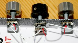
My plan is to investigate if I can use them for an 8 channel DCB1 build. As you can see on the pics one card has bridged pot-holes, and the other varies. The left two has red 2 k variable multi turn resistors, and the one to the far right has 1 k singleturn variable resistors.
I hooked it up on a 5 V supply with a dual 100k pot for starters, and then I hooked up a signal generator and my scope on the in and outputs.

I putted the 2 k variable resistors somewhere half ways and also the 1 k (on 0,5 k) and started sending in 1 V squarewave 1 kHz. It seemed like the outputs has signal to the left and gnd to the right, looking at it from the top. But the channels also seems mirrored so one has input to the left and output to the right and the other one vice versa.
My measures says that the two card with the red variable resistors put to 1 k "works", ie they give an increasing signal when I turn the main 100 k pot. The bridged card and the one with blue pots seems so give very low and not increasing values.

So, some first questions to give me a push on my investigations:
Anyone knows what GB it came from and if there are documentation somewhere?
What suggestions do you have regarding main pot and card mounted pots? Shall I keep the 2 k pots on the boards and try find similar? Shall I decrease value on main pot?
That will be enough for starters")
Best regards
Staffan
I overtook some old project from a friend. I dont know what GB it came from, not how it was matched (or not) and in fact I knew little about the cards so I started to investigate them.
My plan is to investigate if I can use them for an 8 channel DCB1 build. As you can see on the pics one card has bridged pot-holes, and the other varies. The left two has red 2 k variable multi turn resistors, and the one to the far right has 1 k singleturn variable resistors.
I hooked it up on a 5 V supply with a dual 100k pot for starters, and then I hooked up a signal generator and my scope on the in and outputs.
I putted the 2 k variable resistors somewhere half ways and also the 1 k (on 0,5 k) and started sending in 1 V squarewave 1 kHz. It seemed like the outputs has signal to the left and gnd to the right, looking at it from the top. But the channels also seems mirrored so one has input to the left and output to the right and the other one vice versa.
My measures says that the two card with the red variable resistors put to 1 k "works", ie they give an increasing signal when I turn the main 100 k pot. The bridged card and the one with blue pots seems so give very low and not increasing values.
So, some first questions to give me a push on my investigations:
Anyone knows what GB it came from and if there are documentation somewhere?
What suggestions do you have regarding main pot and card mounted pots? Shall I keep the 2 k pots on the boards and try find similar? Shall I decrease value on main pot?
That will be enough for starters
Best regards
Staffan
Thanks George. Shall I stick to dual 100 k? Any wattage to talk about over the board mounted ones? I have some 1 k laying around, I think I read somewhere that its the recommended setup? Unfortunately the once I have is with solder pins in straight line, boards are made for pins with offset on the middle one. I guess theyre 0,25 W or so.
best regards
Staffan
best regards
Staffan
Last edited:
1k .25w is fine but you must use a several watt pot for 100k as long as its running all those boards. See AndrewT's comments a few years back on pot ratings. Assuming 5v at 20mA per ldr is not going to result in a long life for your pot. Maybe a wirewound pot of 3-5w would be a good selection.
Hi George,
I'm close to embarking on the lightspeed journey, just wanted to run couple things by you....i run a Cambridge Audio 640c v2 CD player using wolfson 8740 dac chips direct out via 3.3uf cap,That sounds modded to me I have no idea what the output impedance will be, it needs to be 200ohms or lower
my amp is a sugden solid state which is an integrated but I intend to 'tap in' to the power amp section when using the LSA by-passing the preamp section altogether, not sure what input impedance is but it uses a 50k alps pot as standard if that is any indication??.This 50kohm indicateds that the input impedance to the amp must be higher which is good for the Lightspeed Any observations would be greatly appreciated. Finally I have slight hearing loss in my left ear and wonder would the balance control effect of the trim pot be best way to achieve balance control or better to use 2 pots??Yes the calibration pot can be used to shift the image left or right. Cheers George
Many thanks
Terry Maddocks
Thanks for your response George, appreciated, gonna have to do this I think
Hi all,
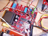
I've just completed my second attempt at building a lightspeed thanks to 4 LDR's that arrived the other day courtesy of Uriah.
It plays at low volume, sounding quite thin, but neither the volume pot or the trimmer pots are having any effect unfortunately. I followed this diagram - just wondering, is the wiring for the pots correct?
apologies for the crap picture
Any advice appreciated. Thanks.
P
I've just completed my second attempt at building a lightspeed thanks to 4 LDR's that arrived the other day courtesy of Uriah.
It plays at low volume, sounding quite thin, but neither the volume pot or the trimmer pots are having any effect unfortunately. I followed this diagram - just wondering, is the wiring for the pots correct?
An externally hosted image should be here but it was not working when we last tested it.
An externally hosted image should be here but it was not working when we last tested it.
apologies for the crap picture
Any advice appreciated. Thanks.
P
Last edited:
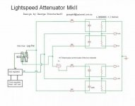
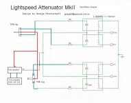
Just saw you are using dual mono volume control (led controlers) this is the circuit for that.
Cheers George
I think that's certainly different to what I've done. I'll give that go. Thanks George.
Gentlemen,
in my eyes (ears) George's "Lightspeed Attenuator" is the best volume attenuation that I have come across in the past,
and I will give it a definite "GO" for my current PCB design (being controlled by an Infrared-controlled motorized potentiometer).
Best regards - Rudi_Ratlos
in my eyes (ears) George's "Lightspeed Attenuator" is the best volume attenuation that I have come across in the past,
and I will give it a definite "GO" for my current PCB design (being controlled by an Infrared-controlled motorized potentiometer).
Best regards - Rudi_Ratlos
Attachments
Last edited:
It plays at low volume, sounding quite thin....
apologies for the crap picture
Any advice appreciated. Thanks.
hope you got it fixed
but gosh.... you really need to look closer at you soldering quality too
please use magnifying glass and check everything carefully
Attachments
got some time over the weekend to get back this. Uriah is right, mine is a 3 pot configuration as in the original schematic posted.
This is what I tried to build:
Uriah, when I originally questioned if it was 'wired correctly' I was referring to the schematic above, but I understand what you're saying - I'll post some more pics of the full build.
I realized George's schematic wasn't quite the same soon after he posted it. I might try that design if I can't get this to work. But for now I'll go back and recheck my build again.
tinitus, yes I know it's a bit of mess but those pots were 'donated' to me from another LS amp and were already scruffy. I'll recheck everything, just wanted to check I'd wired it up correctly in relation to the above schematic.
P
This is what I tried to build:
An externally hosted image should be here but it was not working when we last tested it.
Uriah, when I originally questioned if it was 'wired correctly' I was referring to the schematic above, but I understand what you're saying - I'll post some more pics of the full build.
I realized George's schematic wasn't quite the same soon after he posted it. I might try that design if I can't get this to work. But for now I'll go back and recheck my build again.
tinitus, yes I know it's a bit of mess but those pots were 'donated' to me from another LS amp and were already scruffy.
I'll recheck everything, just wanted to check I'd wired it up correctly in relation to the above schematic.P
The "schematic"/drawing I posted years ago that you show is correct. It was made for folks who have trouble with schematics. The Lightspeed is often a first project. If you rewire anything please use your thinnest wire to be kind to the pots and ldrs. Heat is bad for both and thick wires take more heat. Please make sure the ldr dots are going to negative/0V. Also make sure that the ldr long/round leads go to signal and short/flat go to power. These are often the reason for thin sound because the ldrs are at megohms.
- Home
- Source & Line
- Analog Line Level
- Lightspeed Attenuator a new passive preamp