That is an interesting thought. But my point was also that the gain curve shape of the volume control will be different whenever the input impedance is different.I am not suggesting faking audio taper on an LED/LDR attenuator.
I clearly stated
Yes, well not quite. What does that matter?
Rin of pot at max vol = Pot value // faking resistor // Zin of next stage.
Take the 10k audio law pot and a 20k Zin and the Source sees 10k//20k at max vol or about 6k7
Now substitute a 100k lin pot with a 15k faking resistor.
The 15k is made up from a the Zin=20k + an extra resistor of 56k
The Source sees 100k // 56k // 20k at max vol or about 12k8
Heck that is higher than the impedance presented by the 10k lin vol pot. What is the problem? That the 6k7 rises to 10k at min vol or that the 12k8 rises to 100k at min vol?
I ask again "What does that matter" if the Source is capable of driving the cable and the load at the other end.
Last edited:
Seems to be some confusion here...
Are you guys talking about adding a "faking resistor" to the potentiometer that controls the LED currents in a Lightspeed, or adding it to a normal volume control potentiometer?
If the former, then there's no problem with loading the source component since it's not connected to to it.
If the latter, then why are we discussing normal volume control pots in the Lightspeed thread?
Seems to be some confusion here...
Are you guys talking about adding a "faking resistor" to the potentiometer that controls the LED currents in a Lightspeed, or adding it to a normal volume control potentiometer?
If the former, then there's no problem with loading the source component since it's not connected to to it.
If the latter, then why are we discussing normal volume control pots in the Lightspeed thread?
+1 - This may be really confusing to some folks, especially since it stemmed from the OP comment about using a linear pot to control the Lightspeed LED-LDRs - The complaint was having poor low volume control with a 100K linear pot...
Then discussion switched gears to discuss pots used as passive volume control, with no Lightspeed circuit involvement.
On that subject, this link explains in good detail how to mod a linear pot for log like taper - and sure, I see no reason why one could not give this a try with the Lightspeed circuit, but beware it may require eXperimentation to get right
The Secret Life of Pots
I think there are a few issues.
If we use the faking resistor with the pot that controls the LDRs, then we need to consider how the increased DC current will effect the life of the pot.
If we consider the audio amp example in the LM3886 data sheet and replace the pot with the Lightspeed and add a faking resistor in parallel with the shunt LDR, then the input impedance will be really low.
My last remark did not quote you, it was just a general view of the different options and considerations.I am not suggesting that the faking resistor be added to the LED current control circuit.
I was answering Atupi's question where I thought he wanted to go back to a normal attenuator.
George I was studying the thread so that I may better understand the circuit.
Sorry for asking something that can be noobish. I m just starting to understand how pre and amp are working with each other.
What I was wondering is how does it work that the circuit maitains the same impedance for both input and output.
As an L pad design, I understand that the input impedance stays the same since it's kind of the sum of the series and shunt resistance parts of the LDRs. But on the output side, isn t the amplifier seeing only the shunt impedance?
It behaves very much like a passive 10k dual log pot would, which is also series/shunt. So long as you have an amp with 47k or higher input, the Lightspeed is invisable to it. And so long as the source is 100ohms or less it also is not loaded down by the Lightspeed/Amp combination
Cheers George
Cheers George
.................What I was wondering is how does it work that the circuit maitains the same impedance for both input and output.
As an L pad design, I understand that the input impedance stays the same since it's kind of the sum of the series and shunt resistance parts of the LDRs. ...................
the LED/LDR does not maintain constant resistance/impedance for either the input side nor the output side of the audio circuit.You think a T topology would make any difference? (3 LDRs, 2 series and 1 shunt)
A T attenuator could achieve this, but offers no audio advantage.
I don't see how one could easily use three LED/LDRs in a T format to get that constant input and output impedance with the way the LDRs resistances change with current. Precision of resistance value is paramount to making a T attenuator work properly.
The closest matching available from Silonex will be the NSL32SR2S these are selected version of the NSL32SR2. But you'll still have to to some more matching.
The NSL32SR2S is avaiable from
Search results for "NSL32SR2S" - Allied Electronics
And in England
Buy OptoCoupler Optocoupler; 2.5 V (Max.) @ 16 mA; 25 mA (Max.); 2000 V (Max.); 50 mW (Max.) Silonex NSL-32SR2S online from RS for next day delivery.
Then use one of these and a DMM to do your matching.
Cheers George
Attachments
Last edited:
The closest matching available from Silonex will be the NSL32SR2S these are selected version of the NSL32SR2. But you'll still have to to some more matching.
Then use one of these and a DMM to do your matching.
Cheers George
I have two questions:
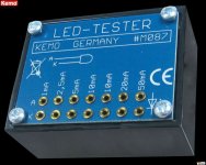
1) I'm curious -- why does the pictured device have two slots for measuring 10ma?
2) On this device, the lowest available current appears to be 1ma. At 1ma the Silonex resistance is somewhere below 200 ohms. In my testing, I've found that LDRs at the upper resistance end (say, at .01ma) can vary by 10K ohms or more. If you match only at currents of 1ma and above, that covers only a small fraction of the useful resistance range of 40 ohms to 10K ohms. What about the preponderance of the resistance range from 200 ohms to 10K ohms that doesn't get matched? Doesn't that require matching?
I use a far more sophisticated setup these days, this is what I used at first over 5 years ago and are quite adequate for the diy'er for matching up quad sets using all 5 ranges from 1 to 20mA to get a close match, then calibrating the last bit further using the trim pot in my schematic with a 1khz sine wave and dual trace scope.
I think the 2 x 10mA holes are a manufacturing defect as they are (on mine at least) both the same.
Cheers George
I think the 2 x 10mA holes are a manufacturing defect as they are (on mine at least) both the same.
Cheers George
2uA to 20mA, in decades, would be a good testing/matching range.
I concede that I'm picking nits here, but since I'm trying to be exacting in my own testing, I believe I would say that more precisely the matching currents should be between 15ma to .015ma, because 15ma gives as good an indication as 20ma without approaching the 20ma limit at the low resistance end, and .015ma is almost exactly the average current value I found to drive about thirty random LDRs to a 10K resistance. (It was actually .016ma, and the range was .007ma to .028ma.) I also like 15ma because that happens to be the maximum current that ever passes through any of my devices, so no LDR is ever stressed at 20ma from testing through operation. For the Lightspeed, 20ma may be preferable for minimum resistance verification.
However, I would also point out that for circuits like the Lightspeed, matching LDRs via current testing is not appropriate; rather, matching should be done at specific voltages, since the Lightspeed is a voltage-controlled circuit rather than a current controlled circuit. LDRs matched at current points will not necessarily match well at voltage points because a given voltage will not necessarily drive the same amount of current through different LDR devices. The voltage required to achieve a specific current flow varies by device. The difference may be considered fairly trivial at high currents, but quickly becomes increasingly important at higher resistances (low current).
For Lightspeed-type circuits, I would stick with precision voltage-controlled matching as the best alternative. But I've never played with a Lightspeed; it's possible that the differences I'm talking about will be too small to matter in the big picture of the overall circuit performance. For my circuit, it does matter so it concerns me.
I consider 10k as the maximum resistance for either of the series or shunt elements as too low. Around the volume midrange, the input impedance will be much lower than 10k.
Further the Lightspeed is not strictly voltage controlled.
The voltage is fixed and the LED/LDR combination react to the interposed variable resistance. I consider that to be much closer to current controlled.
It was for that reason I welcomed the discussion on current control for the LED/LDR volume control, but the thread got bogged down considering only the flawed methods proposed by one Member. A chance missed, but not dead.
BTW, a 30r to 10k LDR resistance range will give a volume range that cannot exceed -0.03dB to -48.8dB when Rin of the next stage is 47k.
Last edited:
- Home
- Source & Line
- Analog Line Level
- Lightspeed Attenuator a new passive preamp