NSL32SR2 needs nowhere near 20mA to hit lower than 40. Did it 12 times today with 12 different NSL32SR2 and only 10mA. The SR2 and SR2S are in fact the same device. After manufacturing some are bagged and some are matched at around 100R to 200R and if they are within 10% of each other they are given an 'S' badge and a letter indicating into which 10% between 100 and 200 they fell into. Also all on the datasheet. However my information does not come to me via the datasheet but from several discussions with the vice president of silonex and their quality control engineer. Obviously I have performed my own experiments on many of these devices. Around 9000 of them now.
Believe what you will, but these are the facts below, and are verified to me by Fred P. Rohrbacher V.P. & General Manager of Silonex a Casco Company, with who I've had many a email disscussion with over the last 6-7 years.
Attachments
...you will also get better logarithmic feel to the volume instead of nothing at the start till you get to 12 o'clock or too much at the start and can't get passed 8 o'clock...
Curious what you are talking about here. What do you mean when you say "you will get better logarithmic feel to the volume instead of nothing at the start til you get to 12 o'clock"?
I ask because a true logarithmic curve is exactly that. It's high attenuation for most of the entry ramp, then rapidly reduced attenuation past the halfway point. This is what log scale means. I must be misunderstanding you somehow.
What do you use for a volume control to drive the LDRs in your circuit?
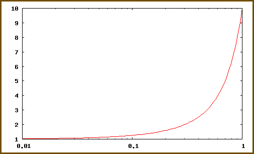
Logarithmic Scale
Exactly what it should be smooth and progressive from zero to 12o'clock then quickly accelerating the level from 12o'clock onwards. (logarithmic). That's what the matched NSL32SR2S quads do with a 100k dual log pot controling the 5vdc to the led's through 100ohm resistors.
Cheers George
Cheers George
Where in there, is the data, to show that "Quad Matching" results in "Lower Minimum Volume"?Andrew:
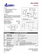
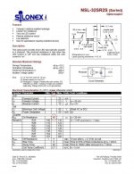
Like I have said all along more times than I care too now (to put it less diplomatically), you will get better lower levels if you use the NSL32SR2S, and when quad matched you will also get better logarithmic feel to the volume instead of nothing at the start till you get to 12 o'clock or too much at the start and can't get passed 8 o'clock. And also more stable impedances which I believe gives a better more consistant sound at different levels also, over the NSL32SR2 or the NSL32SR3. As you have typically 40ohms min value with the NSL32SR2S where the others have well over 100ohms and if anyone pushes these harder than 20mA you will over time end up with a dead led/ldr and that's a given.
Cheers George
I am not referring to any of your other claims.
Last edited:
Andrew stop trying to twist things, you must have a serious weed up your ****. I stated in post 4358. "This is why I use quad matched sets of the NSL32SR2S, to get lower min volume to get better logarithmic feel to the volume and better channel balance."
The data shows the NSL32SR2S has a far lower typical impedance (40ohm) at 20mA led current than the NSL32SR2 or the NSL32SR3 which are over 100ohms typically.
Cheers George
The data shows the NSL32SR2S has a far lower typical impedance (40ohm) at 20mA led current than the NSL32SR2 or the NSL32SR3 which are over 100ohms typically.
Cheers George
Georgehifi,
Since you have replied with 4posts since I asked about that claim, are you deliberately avoiding offering any justification for your claim that "Quad" matching "lowers the minimum volume"?
If you don't show how you have arrived at that, then I'll simply have to conclude that my first impression was correct. Quad matching does not lower minimum volume.
Exactly what it should be smooth and progressive from zero to 12o'clock then quickly accelerating the level from 12o'clock onwards. (logarithmic). That's what the matched NSL32SR2S quads do with a 100k dual log pot controling the 5vdc to the led's through 100ohm resistors.
I've never seen a log pot that produced that curve. All are approximations. It's not terrible, I mean, we've all happily lived with pots for years. But it just seems to me that if you're trying to get away from pots with the LDRs, well, then you would get away from pots.
Not to be nitpicky - I realize your goal is to keep the mechanical wiper out of the signal path. The actual curve of the pot is probably well less of an issue to you. But it does seem to me like part of the problem inherent with mechanical potentiometers is still there.
But it just seems to me that if you're trying to get away from pots with the LDRs, well, then you would get away from pots.
As you may/may not know the pot has nothing what so ever to do with the LDR's or the incoming or outgoing music signal, and with this design the sound quality has always come first.
All it's there for is to control the amount voltage going to the LED's in the simplest, cheapest most convenient manner, if you have a simpler way I'm all ears, KISS.
Cheers George
Having read about various volume control topology and it's gain/position curves published in Wireless World, it seems that linear gain/position is best? Since LDRs already have a near log nature, using linear pots in the Lightspeed already acts like a normal log pot volume control which provide quite linear gain/position relation, but also dependent on the input impedance.
Last edited:
Having read about various volume control topology and it's gain/position curves published in Wireless World, it seems that linear gain/position is best? Since LDRs already have a near log nature, using linear pots in the Lightspeed already acts like a normal log pot volume control which provide quite linear gain/position relation, but also dependent on the input impedance.
Tried that all back a few years ago, you need both the log of the pot and the gain slope of the led/ldr's to get a good smooth progressive feel from down low to mid position. If you use a linear it comes on way to fast from minimum to 10 o'clock position and then there's not much after 12. But then this is with the NSL32SR2S quad matched, It will be different for the NSL32SR2 or the NSL32SR3.
Cheers George
As you may/may not know the pot has nothing what so ever to do with the LDR's or the incoming or outgoing music signal, and with this design the sound quality has always come first.
All it's there for is to control the amount voltage going to the LED's in the simplest, cheapest most convenient manner, if you have a simpler way I'm all ears, KISS.
I was thinking you might like using a digital potentiometer to control the LDRs instead of a mechanical potentiometer. It would also allow you to easily incorporate a remote control.
I was thinking you might like using a digital potentiometer to control the LDRs instead of a mechanical potentiometer. It would also allow you to easily incorporate a remote control.
Thanks for the offer in your PM Wayne, I have looked at this remote path many a time, as it is the production Lightspeed Attenuator has a very very high reliability factor, the only ones that have come back for repair are ones that have been damaged by customers doing weird things, like hooking up car batteries reverse polarity, or being fed massive sine wave voltages on test benches with low impedance loads on the output cooking the ldr's, or just trying to mod them and stuffing things up.
The thing that has always given me concern about going the remote path is the quality of the hand held remotes that are available, and they are not from reliable suppliers (here today gone tomorrow) I have yet to find one cheap enough that would even last a quarter the distance of the Lightspeed Attenuator as it is. And the cost would treble from what it is now, motorized or digital pot, receiver, quality remote, more power supplies, and a bigger chassis to house it all in. Yet the sound quality would remain exactly the same for treble the price? Like I said I firmly believe in the KISS principal in this case.
Cheers George
Accepted, lower "R on" lowers the minimum volume obtainable.it's the NSL32SR2S I'm refering to because it has a much lower "R on" resistance than the other two,
Wayne,
The VCCS (voltage controlled current source) module, originally designed for my own system requirements, uses a digital potentiometer for LED current control and it has additional modules available for remote control. The range of operation can be scaled by resistor selection of R1 to R4 in the current sources to suit the required range of volume control for a given system efficiency. It can be operated by push button controls, either on the preamp chassis or on the remote handset, and provides balance control as well as volume control.
The VCCS module and optional remote control modules were offered as a group buy early in this thread and are still available.
Regards
Paul
Yes, that's more what I was thinking. It is actually much more reliable than a potentiometer. An RDAC will last a lifetime, whereas a potentiometer will probably not. Wipers get dirty and substrates crack. Besides, the RDAC approach allows volume control to be implemented with a true log sequence instead of the crude approximation as implemented on mechanical pots. And of course, there is the ability to incorporate remotes.
Uriah Dailey (BuildAnAmp.com) has chips like this for his version of the LDR attenuator, so you can reach out to him if interested.
Uriah Dailey (BuildAnAmp.com) has chips like this for his version of the LDR attenuator, so you can reach out to him if interested.
Last edited:
Your amp:
" Line-level input sensitivity is 150mV which may lead to rather low settings of the volume control for some source units"
From Review Marantz PM66 KI amplifier (January 1998) - DutchAudioClassics.nl
I think if you put in the extra series LDRs you will be good.
Uriah
Perhapd I'm missing something here. Wouldn't an obvious solution be to add a resistor, say 20K to 40K, in front of the audio input to each series LDR ?
Is the reason this is not suggested, because the LDR "sounds better" than a resistor?
If even a 40K resistor is used, for a 2V rms source, this would still give 400mV rms out at full volume, which for a 150mV sensistive amp should be plenty. In the low end, it would make the control adjust to about -65dB, versus -50 now, and probably be much better.
I would also add, that if that amp puts out 50W into 8ohms with an input of 150mV rms, it has a voltage gain of about 42dB, about 16 dB more than the commonly seen amp gain of 26dB.
By adding 40k in front of the series LDR, you are reducing (i.e. shifting) the sensitivity of the whole attenuator range down 15dB, and you will make it work similar to a "normal" gain amp.
By adding 40k in front of the series LDR, you are reducing (i.e. shifting) the sensitivity of the whole attenuator range down 15dB, and you will make it work similar to a "normal" gain amp.
- Home
- Source & Line
- Analog Line Level
- Lightspeed Attenuator a new passive preamp