

Hi guys,
I wonder if someone can help me. I built a Lightspeed over a year ago but was not able to get it working properly. I spent today revisiting the project, rebuilding, recalibrating and testing but with the same results. Everything seems to check out as far as balancing the shunt LDRs according to the build manual, and the volume control does work and it sounds great, but the minimum volume is far too high - it's actually just slightly louder than my 'doing the dishes' listening volume. I'm sure I've probably just made a mistake somewhere, but I've hit a dead end figuring what it could be.
Rather than building a standalone pre-amp, I'm trying to install in my integrated amp in place of the original 50k pot. I'm using a 100k pot for testing, but would ideally like to use the amp's 50k pot instead. The Lightspeed sits between the input DC blocking caps and the amp's pre-amp input.
I've taken some measurements with my DMM in the hope that they might hold some clues as to what might be going wrong. As I said, the LDRs balanced fine as per the instructions. In the completed circuit, I observed the following: The resistance on each channel between in and out measures in the range of 160 Ohms (max volume) to 10 kOhm (min volume). The resistance between input and ground is around 10k at both extremes, but sinks to around 7k at half way. The resistance between output and ground ranges between around 30 Ohms (max volume) and 10kOhm (min volume).
Any advice anyone can offer would be very much appreciated.
Cheers,
Ben
Edit: By the way, I tried installing the Lightspeed in addition to the existing Alps pot for testing. I tried both attenuators with the other fully open, and my impression was that there was far better sound with the Alps at max and the Lightspeed at min than at the same level achieved by setting the Lightspeed to max and using the Alps pot to attenuate to the same level. The only problem is the minimum is far too loud.
Last edited:
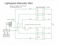
As you are already aware the attenuator changes volume by changing the ratio of the upper and lower LDR resistances.
At max volume the upper LDR's are at lowish resistance anywhere from 100r to 1k, you'll see later why that does not matter.
The lower LDRs are at highish resistance. Let's guess at 30k.
The attenuation for 100r to 30k is 20 * log(30k/[30k+100]) = -0.029dB
and for 1k to 30k is 20 * log(30k/[30k+1k]) = -0.284dB
Essentially the maximum volume is the same whether the upper LDR sits at 40r or 100r or 1000r.
Now let's consider minimum volume.
Lets again assume a maximum resistance of 30k, but this time for the upper LDRs.
The lower LDRs could be set to 100r or 1000r (1k).
The maximum attenuation is 20 * log(100/[100+30k]) = -49.57dB
and for 1k is -29.83dB
The maximum attenuation using the lowest reliable 40r for the upper LDR resistance is -57.51dB
The effect on minimum volume is critically linked to the minimum resistance of the upper LDRs.
You must set the upper LDR currents to get the lowest volume you require, but still stay within the reliability limit of >=40r.
That 40r is achieved by increasing the LED current using the ~100r resistors.
If you want lower minimum volume then check the voltage across the limiting resistors and calculate the LED currents at your minimum volume setting.
Compare your highish LED currents to the recommended High current setting of the LEDs.
That is where your setting up problem is.
Be very careful how you trim the 100r to approach the 40r minimum of the LDRs. Don't accidentally make the 100r too low, or you risk damaging the LED/LDR
Ben you did it right. The numbers you show are what is expected. A typical build. The problem you are having is that your system is far to efficient and has far to much gain for the Lightspeed. Your speakers must be very efficient and perhaps you are using a gainclone or another high gain amp. Also its possible that you might be using a source with a higher than average output voltage but thats less likely than the other two.
My suggestion would be to get two more LDRs. Put them in series with the other series LDRs and dial the new ones up in resistance until low volume is actually low. Then leave them there and use the Lightspeed for volume change. This will lower your max volume, but for you I dont think that will be a problem.
Uriah
Hi guys,
but the minimum volume is far too high
- Ben
This can happen if the circuit is not as mine posted with matched quads (series & shunts), not a matched pair of shunts and a matched pair of series. As well as having a more logarithmic feel to the volume control with matched quads.
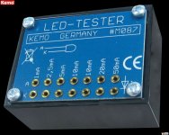
And get yourself one of these with a dmm to do the quad matching with at 1 2.5 5 10 & 20mA, and you'll have perfect channel balance from low to high, couple of dollars at the electro shops.
Attachments
The man has 4 LDRs. 2 Pairs. The matching between A and B of one pair is great and then matching between the two pairs is likely within 100R maybe a few hundred more at max which has zilch to do with min volume. Its got to do with shunt resistance and the gain of his system. Can someone please tell me why that is technically incorrect? Its not.
PS my testing of LDRs goes to somewhere between 5k-10k as the max resistance on the LDRs. My matching is done with real life currents that will be used at max and mi n volume and ranges in between. Max and min require max and min current. Min current in my testing goes as low as .0001045A and is necessary to test LDR at max resistance.
Why has this turned into this? Help the man out, dont confuse him.
Last edited:
5v/5000R=1mA or 5% of the volume use on a 100k pot that is adjusting current. 1mA as min testing current IMHO is not low enough.
LDRs that test the same at the first few hundred ohms of their resistance do not necessarily or even usually test the same at min current. Even if they are the S series, sorted. I could post dozens of excel spreadsheets to prove this point.
LDRs that test the same at the first few hundred ohms of their resistance do not necessarily or even usually test the same at min current. Even if they are the S series, sorted. I could post dozens of excel spreadsheets to prove this point.
Last edited:
LDRs from a test batch of 120. None of these LDRs made it to be sold. Their first number, highest current, has obviously naught to do with the next 3 numbers. The first number is at less than a mA.
These are all throw aways.
155 1571 2737 6521
176 1643 2771 6215
184 1557 2516 5591
188 2021 3755 8909
189 2457 3893 11373
195 2180 3943 9700
197 1932 3418 8002
205 1627 2706 5740
205 1923 3217 7137
207 1773 3027 6636
219 2628 4983 12270
242 3734 7580 23300
244 1618 2765 6162
248 3377 6352 16230
250 3121 5656 13900
253 2869 5089 12496
255 2184 3689 8405
256 1859 3212 7154
256 2884 5360 13300
257 2502 4613 11149
269 2021 3401 7488
277 2711 4608 10261
283 1971 3065 6174
289 2227 4041 9519
292 2484 4354 10081
301 2953 5227 12620
304 2771 4938 10820
306 3246 5505 12512
310 2981 5104 11250
312 3942 7030 17359
314 3435 5884 13882
318 3504 6159 14927
322 1782 2974 6860
373 3239 5732 14118
Thanks for your replies, everyone. I'm still reading through it all, but I think it's worth saying that I feel as though it should be possible to rule out any outlandish operating environment presented by my equipment. My loudspeakers are probably the easiest to eliminate because of their unremarkable efficiency rating of 88dB. My amp and CD player, while heavily tweaked for sound quality, should not differ much in terms of their respective gain and output voltage from their original mass-market specifications.
Your amp:
" Line-level input sensitivity is 150mV which may lead to rather low settings of the volume control for some source units"
From Review Marantz PM66 KI amplifier (January 1998) - DutchAudioClassics.nl
I think if you put in the extra series LDRs you will be good.
Uriah
" Line-level input sensitivity is 150mV which may lead to rather low settings of the volume control for some source units"
From Review Marantz PM66 KI amplifier (January 1998) - DutchAudioClassics.nl
I think if you put in the extra series LDRs you will be good.
Uriah
This confirms the min volume LED currents at 16mA and 20mA.The voltage over the 100R limiting resistors at min volume is 1.6v and 2.0v.
Something wrong here.
5V from the regulator.
1.9V across the LEDs and 1.6V across the 100r.
Where has the other 1.5V gone awol?
Can anyone confirm if it is safe to reduce the 100r slightly, to increase the LED current and thus decrease the LDR resistance below the existing measured 30r?
-50dB and 150mV sensitivity is the compatibility problem.
adding a pair of series LDRs will increase your max attenuation to ~-56dB
Or
adding a pair of shunt LDRs will increase your maximum attenuation to ~-50dB
Or
adding both a pair of series LDRs and a pair of shunt LDRs will increase the maximum attenuation to ~-62dB.
It is far easier to increase the impedance of your 100k control pot to increase the LDR resistances to far above the 10k you have measured. Try for LDR~50k or even ~200k.
You can do the equivalent to the high value control pot by instead reducing the regulated voltage from 5V to ~3.5V. This roughly reduces LED current by ~ 50%. Then you will definitely need to reduce the 100r resistors.
Last edited:
I find that below 40R the LDRs start to lose matching so I dont go lower. I cant say for certain what current because I use the resistance of the LDR as my guide. I dont like to see numbers like 30-34. I dont mind 35 and up to much but like to stick at 40 and up.
You could do similar to AndrewT's suggestion and stick a few trimmers after the current limiting resistors for the series LDRs and raise max resistance of LDRs by raising resistance of these trimmers but this will limit your max volume. You could make another LDR voltage divider that never moves, static rather than dynamic LDR resistances. These will all work.
Taking the LDRs up to 50-100k is possible but guaranteed to not match any longer. If you dont mind using a balance pot this is fine.
I think the easiest to try right now is reduce voltage and see if it solves your problem. You should still have same or real close to same min resistances this way.
Uriah
")
The resistance of my LDRs measures as follows:
Shunt / Series
Min: 30R / 10k
Max: 10k / 160R
I think by Andrew's math that sets max attenuation at -50dB.
The voltage over the 100R limiting resistors at min volume is 1.6v and 2.0v.
Look at the Silonex data spec sheets. This is why I use quad matched sets of the NSL32SR2S, to get lower min volume to get better logarithmic feel to the volume and better channel balance.
On resistance of a NSL32SR2S is typically 40ohms @20mA
On resistance of a NSL32SR2 is max 40ohms @ 20mA, typically much higher >100ohms
On resistance of a NSL32SR3 is max 60ohms @ 20mA, typically much higher >100ohms
Cheers George
George,..............I use quad matched sets of the NSL32SR2S, to get lower min volume
Can you show your data to justify your claim that "quad" matching achieves "lower" minimum volume.
Basically, I put it less diplomatically, I don't believe this claim.
Andrew:
Like I have said all along more times than I care too now (to put it less diplomatically), you will get better lower levels if you use the NSL32SR2S, and when quad matched you will also get better logarithmic feel to the volume instead of nothing at the start till you get to 12 o'clock or too much at the start and can't get passed 8 o'clock. And also more stable impedances which I believe gives a better more consistant sound at different levels also, over the NSL32SR2 or the NSL32SR3. As you have typically 40ohms min value with the NSL32SR2S where the others have well over 100ohms and if anyone pushes these harder than 20mA you will over time end up with a dead led/ldr and that's a given.
Cheers George
- Home
- Source & Line
- Analog Line Level
- Lightspeed Attenuator a new passive preamp