Yeah, ignore what I said. I saw the diodes and ignored them, not realizing they were the LED side of the LDR.
Looks like a fun circuit but also looks like the post from 1360 is more obvious how to operate it than the one posted a few posts back as with the latest post we dont see how to individually manipulate the LDRs.
Do you see how to manipulate the channels individually as in post 1360? I think R3 and R4, if they were trimmers would help you.
Uriah,
Nelson's design only attenuates about 35dB attenuation, unlike your "full range" units, and the buffer here isn't out familiar B1, but the complementary k170/j74 one - apart from that and the higher impedance range of the S3 ldes, it works in the same way, so operating them in parallel with variations of the 431 current distribution (ie balance trim) shouldn't present any problems.
Zum, for that imbalance, assuming matched devices, just measure the voltages at the led ends and if they're the same, check for a bodgie resistor, especially the pot.
Thanks all for the help. I matched the ldr's as best as I could from the batch I had. As they are wired in series, I can't figure how to trim them individually. I suppose I could swap the ldr's around to find a better balance but wanted to avoid heating them too much. The imbalance is not too bad, about 7 percent measured difference, and on some music not noticeable so I might just learn to live with it.
Cheers
Rick
Cheers
Rick
hey George, where did you find that one ?
Can't remember tinitus, in was in my files maybe Nelson sent it to me?
Cheers George
Deep in the thread you'll see NP posted variations on the LDR design as an attenuator...the attached (post# 3443) is a re-drawing of his design for a better (IMHO) understanding...so is the "much improved" schematics of the Lightspeed that George uses to post every now and then...even a half-hearted credit for the little help will be nice

Uriah,
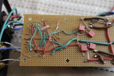
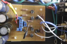
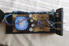
Here's some images. A bit of rat's nest but it works. I originally had the buffer on the output but have changed to the input to use with my CD player that has a higher Zo. Both ways I had the same imbalance.
Cheers
Rick
Here's some images. A bit of rat's nest but it works. I originally had the buffer on the output but have changed to the input to use with my CD player that has a higher Zo. Both ways I had the same imbalance.
Cheers
Rick
Attachments
After pouring over 100+ pages in this forum thread I bought a matched set of LDRs and a 100k ALPS pot and fired up the soldering gun. I wired up my own board and popped it into a home made passive preamp replacing the existing 20k ALPS Blue Velvet volume control pot.
I've been reading how much a volume pot influences the sound and frankly have been skeptical.....just another exaggerated audiophile claim that only golden ears can discern. But HOLY COW, I'm hear to tell you the difference between a pot and LDRs is not subtle. It completely changed the sonic quality of my rig for the better. Everthing became smoother and more natural sounding with less harsh high end, better overall tonal balance and deeper sound stage.
Anyway, thought I'd add my big thumbs up vote on LDR volume control.
The only negative is I can't turn the volume down to zero but the low end level is acceptably low.
My rig:
Squeezebox Duet digital out
Music Hall 25.2 DAC (with Mazda tube)
Passive Preamp w/ LDR volume control (home made unit)
Ashly XR-2001 active crossover (3 way)
Pair of homemade 3 channel 120 w/channel gainclone power amps
Pair of homemade GR Research tri-amped OB-7 speakers
Single Rythmik A370PEQ servo subwoofer in homemade box
Hi George, hi Udailey, hi to all music enthusiasts,
I bought a matched set of LDRs from udailey (I think are not 4 full matched set but a set of 2 + 2).
I have a valab tda1543 DAC with 2vout and 260ohm output impedence at 1khz, 1pot 100kohm log stereo, 100ohm resistors before LDR like MkII design and a very high gain amplifier like Primaluna Prologue 2.
My problem is that with my volume pot (minimun value it's six o'clock) I have already at seven or eight o'clock an enormous changed on volume level. At nine o'clock is very very louder.
With all your suggestions taken in this forum I can't have a solution.
The only mode that functions is to make a 150kohm resistor with 1 side to my 5volt PSU and the other side to the 5volt input on pot, but I think it's not a good solution.
thank you very much to all
Andrea
Last edited:
Hi arnold23,
Check out the VCCS module (details on post 1874 page 188). This module provides a voltage controlled current source (VCCS) for each LDR LED. The operating range can be tailored to suit your system by changing the resistance values of resistors R1 to R4. The VCCS module provides volume up/down and balance. You can also add remote control if you wish.
Regards
Paul
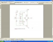
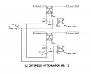
I have had a difficult time understanding the (admittedly simple) layout of the Lightspeed attenuator, particularly the purpose of the LOG taper potentiometer and the impact of using different values of pot. I finally drew it out for myself, and now I get it. In case someone else would benefit from a seeing it from a different view, here it is.
Attachments
Last edited:
Hi George, hi Udailey, hi to all music enthusiasts,
I bought a matched set of LDRs from udailey (I think are not 4 full matched set but a set of 2 + 2).
I have a valab tda1543 DAC with 2vout and 260ohm output impedence at 1khz, 1pot 100kohm log stereo, 100ohm resistors before LDR like MkII design and a very high gain amplifier like Primaluna Prologue 2.
My problem is that with my volume pot (minimun value it's six o'clock) I have already at seven or eight o'clock an enormous changed on volume level. At nine o'clock is very very louder.
With all your suggestions taken in this forum I can't have a solution.
The only mode that functions is to make a 150kohm resistor with 1 side to my 5volt PSU and the other side to the 5volt input on pot, but I think it's not a good solution.
thank you very much to all
Andrea
First, its a matched set unless you bought them mid year last year or earlier.
Second, there are several reasons for volume being very loud. This may be the taper of the LDRs you have. You may be using a linear 100k dual pot rather than a log. You may have an amp with enormous gain or exceptionally efficient speakers.
We need more information and pictures of your Lightspeed will be helpful. These pictures should be complete enough that we can understand exactly how you built your Lightspeed.
@Wapo
You need one more 1k trimmer if you would like to have balance control, or, you should explain in your schematic that the 1k is only intended to be on the loud channel. Also if you would emulate George's MKII you will need a dual log pot rather than a single gang.
Uriah
Arnold,
Still tired from staying up late listening to music. I missed the part about your amp. Yes a really high gain amp will get loud very early. This is the situation with my high gain amp and high efficiency speakers as the LDRs already start at a minimum of 40Ohms and then mine jump to about 70Ohms nearly instantly. There is quite a difference in volume especially since at the same time the series LDRs are dropping very quickly. They will then smooth out and volume change will be more smooth but at first turn the change is dramatic.
Your solution may not be perfect but it might be great for your system. Can you use your DMM on One Series LDR and tell me its max resistance and min resistance and then do the same thing on One Shunt LDR.
@Wapo
You need one more 1k trimmer if you would like to have balance control, or, you should explain in your schematic that the 1k is only intended to be on the loud channel. Also if you would emulate George's MKII you will need a dual log pot rather than a single gang.
Uriah
Uriah, you are right -- there is more than one version of George's circuit in the thread. I can easily add/fix the items you point out, just give me a minute . . .
While we are posting schematics and helping folks out I should repost my instructions for building one. Although it uses my little board for mounting LDRs you sure dont need the board, its just easier. Perfboard like on page 345 works great to. I had a mistake in the explanation. The guy that put together the doc interpreted the pot as a voltage divider and while it is in other cases a voltage divider, it works a little differently in this circuit. So that correction was added.
Google Docs
Google Docs
Uriah, you are right -- there is more than one version of George's circuit in the thread. I can easily add/fix the items you point out, just give me a minute . . .
My 30 minute edit window has expired so I can't change the original, and your updated instructions contain the circuit you want people to use, so I would ask Tinitus to simply delete my schematic at his convenience.
Last edited:
I want people just to use LDRs. If they use my little boards with my circuit thats fine but mostly I just want them to take a chance and try something that sounds like its snake oil only to find out that sometimes it really can be as good as all the claims. If you have a circuit show it. And if you now get how it works I think thats fantastic. You can help others on this thread now. I dont mean to seem like I am pushing you out of the way, its just coincidental that he emailed me the corrected pdf last night and since this is the first time back to the thread since then I am now posting it.
- Home
- Source & Line
- Analog Line Level
- Lightspeed Attenuator a new passive preamp