ROFL! This is the sort of thing I normally get into, it's great to see someone else do it for a change! ")
Gentlemen, I believe the technical term for the package is "optocoupler" within said package exists an LED and an LDR.
I think the statement that confused Andrew -- because it confused me, too -- was that you had a CCS fed by a low-voltage regulated supply. Also, I could not see how a CCS could be used in a situation where the whole point was to make the current changeable by introducing variable resistance in the form of a volume control potentiometer.
Upon reflection, it sounds like the CCS limits maximum current to the 10ma, and then the regulated 5V supply prevents the CCS from working to keep current steady when system resistance is increased via the volume control potentiometer. Have I got it right?
BTW, 10ma looks like about 60 ohms minimum resistance on the Silonex chart, is that what you are getting with your devices?
Voltages and currents
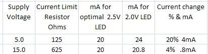
Folks, look at the attached bit of spreadsheet, it will demonstrate something that may not be well understood.
Make the following assumption: you have two optocouplers (LDRs!! ) that you are using as a pair. Power-wise, they are not well matched -- one consumes the target 20ma at the standard 2.5V, but the other is at the outside of tolerances, and consumes 20ma at only 2.0V.
OK, now look at the consequence of using a low voltage like 5.0V to run this circuit, as compared to a more desirable 15 volts. These two LEDs will produce much different power consequences at different power supply voltages. The point is that at the lower supply voltage, the LED voltage is much more critical than it is at a higher voltage and with a higher value current limiting resistor in the circuit.
It appears to me as though the current mismatch problem would tend to go away if you would start out with a higher voltage supply and use a larger value resistor as a current limit.
The reason for this difference is that as a percentage of the total circuit resistance, the LED is a much higher percentage at the lower voltage with lower value limit resistor than it is in the higher voltage circuit. Thus, any minor change in the voltage drop across the LED has a much greater overall percentage effect on the circuit as a whole at lower voltages.
It seems to me that everyone who uses a Silonex optocoupler would be better off with a higher voltage regulated source and a higher value current limit resistor, since this would reduce the current differences between devices.
Is there a flaw in my math somewhere, or have I got it right?
Folks, look at the attached bit of spreadsheet, it will demonstrate something that may not be well understood.
Make the following assumption: you have two optocouplers (LDRs!!
) that you are using as a pair. Power-wise, they are not well matched -- one consumes the target 20ma at the standard 2.5V, but the other is at the outside of tolerances, and consumes 20ma at only 2.0V.OK, now look at the consequence of using a low voltage like 5.0V to run this circuit, as compared to a more desirable 15 volts. These two LEDs will produce much different power consequences at different power supply voltages. The point is that at the lower supply voltage, the LED voltage is much more critical than it is at a higher voltage and with a higher value current limiting resistor in the circuit.
It appears to me as though the current mismatch problem would tend to go away if you would start out with a higher voltage supply and use a larger value resistor as a current limit.
The reason for this difference is that as a percentage of the total circuit resistance, the LED is a much higher percentage at the lower voltage with lower value limit resistor than it is in the higher voltage circuit. Thus, any minor change in the voltage drop across the LED has a much greater overall percentage effect on the circuit as a whole at lower voltages.
It seems to me that everyone who uses a Silonex optocoupler would be better off with a higher voltage regulated source and a higher value current limit resistor, since this would reduce the current differences between devices.
Is there a flaw in my math somewhere, or have I got it right?
Attachments
Last edited:
was that you had a CCS fed by a low-voltage regulated supply. Also, I could not see how a CCS could be used in a situation where the whole point was to make the current changeable by introducing variable resistance in the form of a volume control potentiometer.
-----
i must have a serious problem in communication. however i did say i used the LDR for source switching instead of attenuation.
-----
i must have a serious problem in communication. however i did say i used the LDR for source switching instead of attenuation.
-----
i must have a serious problem in communication. however i did say i used the LDR for source switching instead of attenuation.
Hot Darn!!! So you did . . .
May I ask for you opinion about the "sound" of LDRs -- how it affected your system when you switched to LDR input switching? Did you hear a difference? If so, what was that difference?
Last edited:
Look, I know I sell them and everything so I am supposedly financially biased but they sound better than frankly any preamp I have heard. I just took an LDR preamp to the Lonestar Audio Fest. I got stuck on a floor of the hotel where the conference was at that nobody visits. We show our stuff out of our hotel rooms. So anyway, I said screw it and put the preamp under my arm and went to other guys rooms. Its friendly that way and no one minds. I stuck it in two systems that day. Both guys bought one. Both guys have been speaker manufacturers since the mid 80's. Both said nearly the same exact phrase " I have been professionally building speakers since "86" and I have never heard them sound so good."
They really are that good. They are only a few bucks each. The circuit is easy even on perfboard. You have to try it. Its no use sitting here analyzing nothing. Well, actually it is. Your idea of analyzing them is intriguing, but in the meantime man build the attenuator.
Uriah
They really are that good. They are only a few bucks each. The circuit is easy even on perfboard. You have to try it. Its no use sitting here analyzing nothing. Well, actually it is. Your idea of analyzing them is intriguing, but in the meantime man build the attenuator.
Uriah
they sound better than frankly any preamp I have heard.
Uriah
Uriah, everything I've read here suggests they sound terrific, and I accept that as a working hypothesis. However, there are vanishingly few posts (there may be some, but I can't remember any, and I've read the whole thread!) that actually describe the phenomenon. I want someone to describe what they sound like!
Asking for someone to describe their experience is not the same as doubting the phenomenon. I'm just asking for something I can wrap my mind around that isn't just "it's great!!"
Optocoupler is an IC
I have been corrected on that issue before
LDR / light dependent resistor is correct term
Why not just stick to that
Tinitus, an optocoupler as discussed in this forum is not an IC. From Wikipedia: In electronics, an integrated circuit (also known as IC, microcircuit, microchip, silicon chip, or chip) is a miniaturized electronic circuit (consisting mainly of semiconductor devices, as well as passive components) that has been manufactured in the surface of a thin substrate of semiconductor material.
The device we talk about here is not an integrated circuit -- it is merely two discrete devices glued together in a light-tight housing, and they are not integrated. PerkinElmer and Clare manufacture other similar devices that actually are integrated circuits because the enclosure includes integrated transistors for amplification and other duties.
if you would look at the published Silonex and PerkinElmer documentation, you will see that Silonex describes this device as an "optocoupler" and PerkinElmer describes it as an "Optoisolator (Vactrol)." Neither manufacturer describes it as an LDR (light dependent resistor) because that term is already taken to describe a two-wire device typically made with cadmium sulfide (CdS). In the Silonex and PerkinElmer packages, there are indeed LDRs glued together with LEDs, but the entire package cannot technically be described as a simple LDR.
This is a pretty loose forum because there are folks here with a variety of technical backgrounds, and that's great. Not everything described here is technically correct, and that's fine, it is what it is. But it's not fair to try to legislate facts to be accepted which are not actually factual.
Uriah, everything I've read here suggests they sound terrific, and I accept that as a working hypothesis. However, there are vanishingly few posts (there may be some, but I can't remember any, and I've read the whole thread!) that actually describe the phenomenon. I want someone to describe what they sound like!
Asking for someone to describe their experience is not the same as doubting the phenomenon. I'm just asking for something I can wrap my mind around that isn't just "it's great!!"
I hear ya. I am just not a man of many adjectives. I agree with the man with 3 Gs in his name. Transparent. Also really smooth.
Tinitus, an optocoupler as discussed in this forum is not an IC.
He knows
May I ask for you opinion about the "sound" of LDRs -- how it affected your system when you switched to LDR input switching? Did you hear a difference? If so, what was that difference?
-------
i have to confess that i've not had any extensive subjective evaluation of LDR as an attenuator. the brief section i had didn't leave any negative effect. i gave up the idea when i measured them as an attenuator. as a switching element, it differs very slightly from my relay setup.
but i think LDR is so cheap and simple. it is not much point to listen to someone else opinion before trying it out. i have been so disappointed with so many so called excellent audio systems. i tend to ignore most subjective experience nowadays.
A few weeks ago I was involved with an ABX comparison of a Lightspeed and a ME24 preamp and the result was... ABX tests are a pain.
At the end of the long testing session we used a very high end CD player, the Lightspeed and some active speakers (which in theory aren't ideal with passive pres) and the results were very enjoyable. The Lightspeed certainly shines when using high quality hifi components.
I must finish building mine.
regards
At the end of the long testing session we used a very high end CD player, the Lightspeed and some active speakers (which in theory aren't ideal with passive pres) and the results were very enjoyable.
The Lightspeed certainly shines when using high quality hifi components.I must finish building mine.
regards
Tinitus, an optocoupler as discussed in this forum is not an IC. From Wikipedia: In electronics........
But it's not fair to try to legislate facts to be accepted which are not actually factual.
Let not mess more with that subject
optocoupler - Google Search
as I understand it, LDR might be called optocouplers when used as switches
http://www.jaycar.com.au/images_uploaded/optocoup.pdf
but used as a variable resistor, its just an LDR
i have been so disappointed with so many so called excellent audio systems. i tend to ignore most subjective experience nowadays.
I hear you, thanks for the reminder of that, I think I won't ask for opinions any more.
Let not mess more with that subject
Noblesse oblige.
EDIT: I need to get away from here for a while. I'll post again when I have my T attenuator working.
Last edited:
Good progress today, validated my control system successfully, this is going to work.
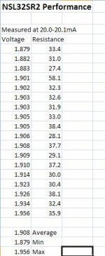
Measured the batch of optocouplers I got from Uriah, spreadsheet attached.
Bottom line:
These devices have a voltage drop across the LED (@ 20ma) that runs from 1.879V to 1.956V, average 1.908V.
All devices except one measured below 40 ohms at 20ma.
The proper current limit resistor for this device is 150 ohms, based on a 5V supply with 1.95V dropped across the LED, and the remaining 3.05V dropped across the limit resistor. 3.05V across a 100 ohm resistor will deliver just over 30 milliamps, and 3.05V across a 150 ohm resistor will deliver 20 milliamps.
Attachments
- Home
- Source & Line
- Analog Line Level
- Lightspeed Attenuator a new passive preamp